
Datasheet & Wiring diagram Of ANT BMS ANT-24ADA/24ADC 13S-24S 100A-200A JNFN BMS
一、产品概述(Product Overview)
The ANT-24ADA/24ADC is an active balancing protection smart board launched by ANT BMS, supporting 13-24S configurations. It features a maximum balancing current of 1A, along with characteristics such as compact size, low power consumption, and high-efficiency balancing. The device has built-in Bluetooth and supports multiple communication methods.
二、规格参数 / Technical Specifications
- 基础规格(Basic Specifications)
| 项目(Item) | 内容描述(Description) |
|---|---|
| 支持电芯(Supported Cell Types) | 三元、铁锂、钛酸锂 Ternary, LFP, LTO |
| 电池组串数(Number of Battery Strings) | 三元:13-21 串、铁锂:13-24 串、钛酸锂:13-24 串 Ternary: 13-21 strings, LFP: 13-24 strings, LTO: 13-24 strings |
| 均衡方式(Balancing Method) | 主动均衡 Active Balancing |
| 单体采样电压范围(Single Cell Sampling Voltage Range) | 1V-5V 1V-5V |
| 采样频率(Sampling Frequency) | 均衡状态:1 Hz,非均衡状态:4 Hz 1 Hz during balancing, 4 Hz when not balancing |
| 单体电压采集精度(Single Cell Voltage Measurement Accuracy) | 3mV 3mV |
| 工作电压范围(Operating Voltage Range) | 24V-96V 24V-96V |
| 电流采集范围(Current Measurement Range) | 0-420A 0-420A |
| 电流采集误差(Current Measurement Error) | ±2% ±2% |
| 工作功耗(Operating Power Consumption) | 小于 1.5mA <1.5mA |
| 待机功耗(Standby Power Consumption) | 小于 0.6mA <0.6mA |
| 工作温度(Operating Temperature) | -40℃-85℃ -40℃-85℃ |
| 产品重量(Product Weight) | 约 220g Approx. 220g |
2. 电流规格(Current Specifications)
| 产品配置 / Configuration | 产品型号 / Model | 放电持续电流 / Continuous Discharge Current | 放电持续时间 / Continuous Discharge Duration | 放电峰值电流 / Peak Discharge Current | 峰值持续时间 / Peak Discharge Duration |
|---|---|---|---|---|---|
| 加强款 | BA01A24E10A | 100A | >1H / >1 hour | 250A | 1min |
| 加强款 | BA01A24E12A | 120A | >1H / >1 hour | 300A | 1min |
| 加强款 | BA01A24E15A | 150A | >1H / >1 hour | 375A | 1min |
| 加强款 | BA01A24E18A | 180A | >1H / >1 hour | 450A | 1min |
| 加强款 | BA01A24E20A | 200A | >1H / >1 hour | 500A | 1min |
三、操作说明 / Operating Instructions
1. 保护板安装及接线 / BMS Board Installation and Wiring
① 焊接采样排线
Solder the Sampling Ribbon Cable
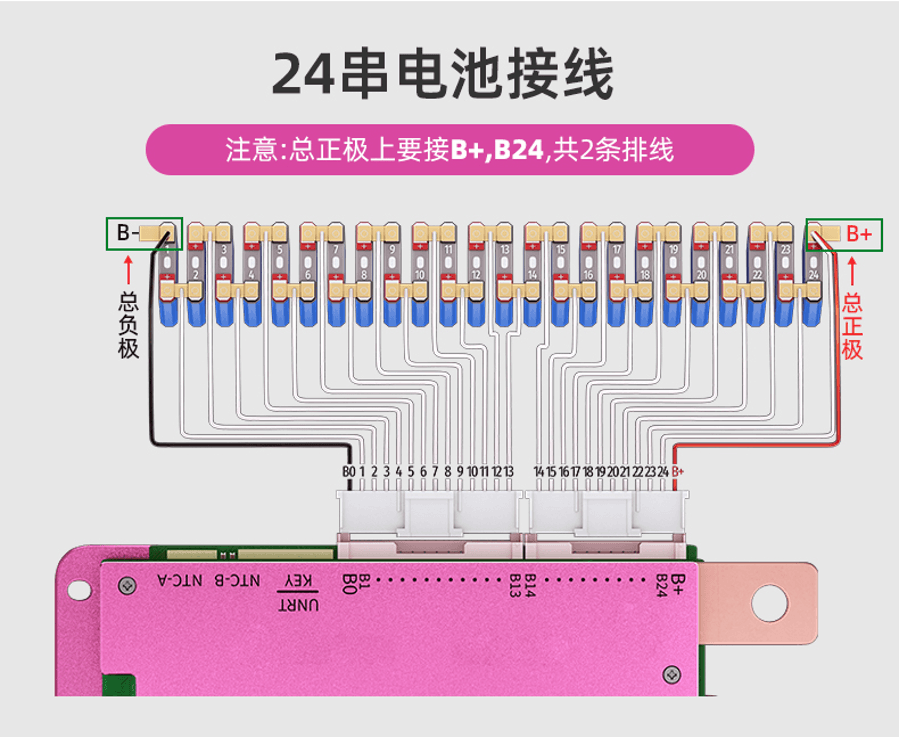
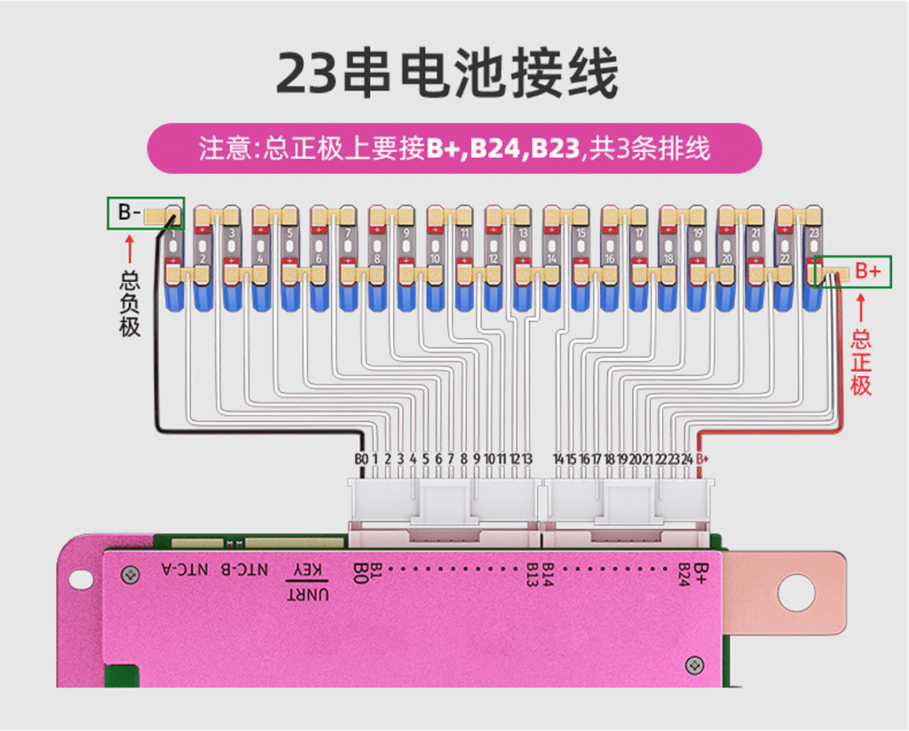
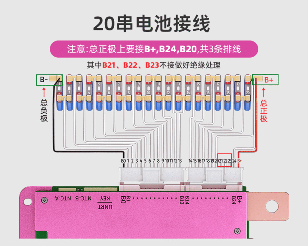
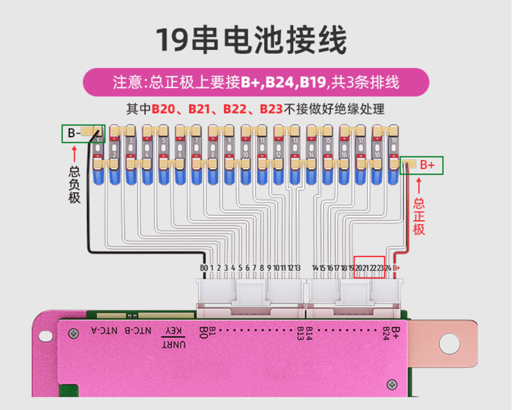
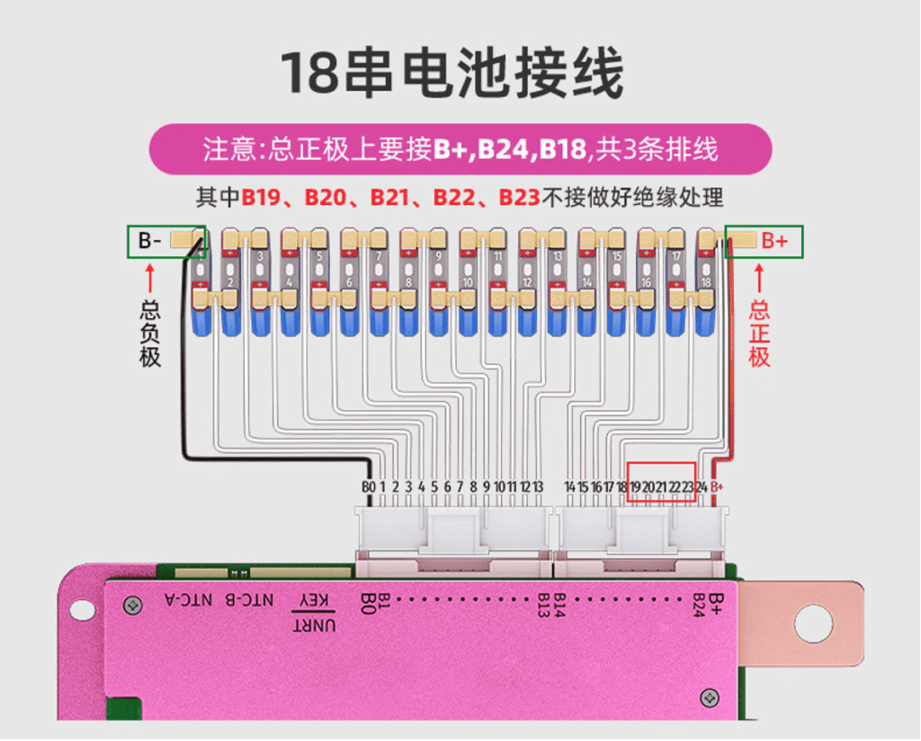
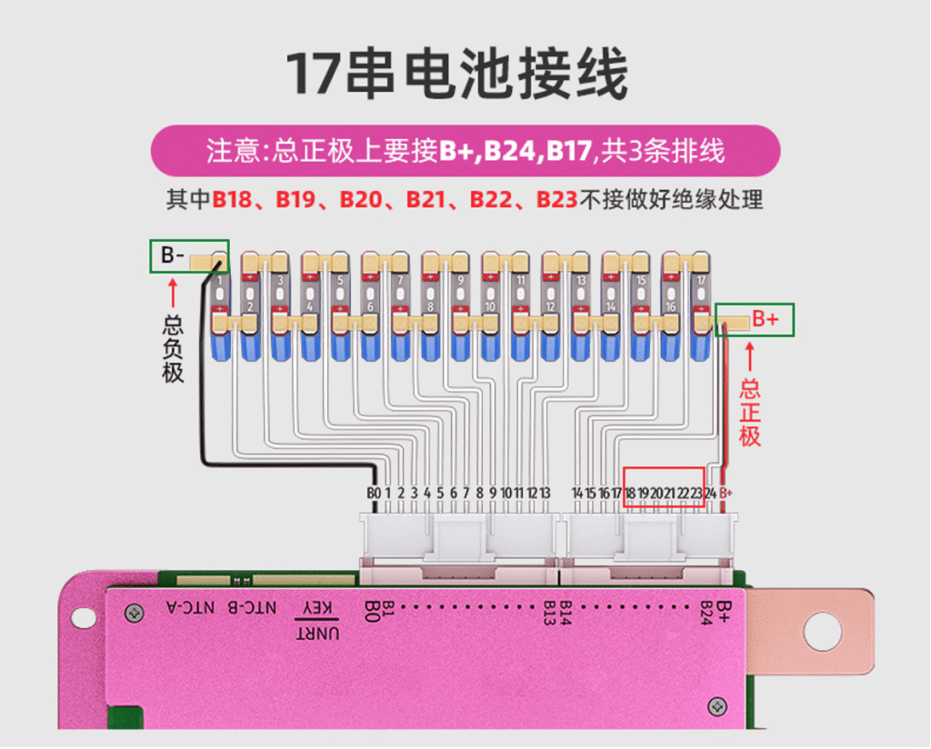
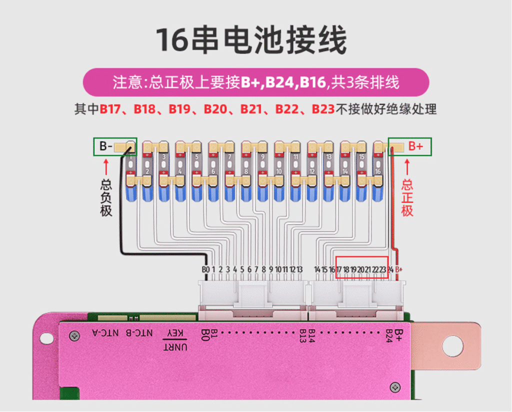
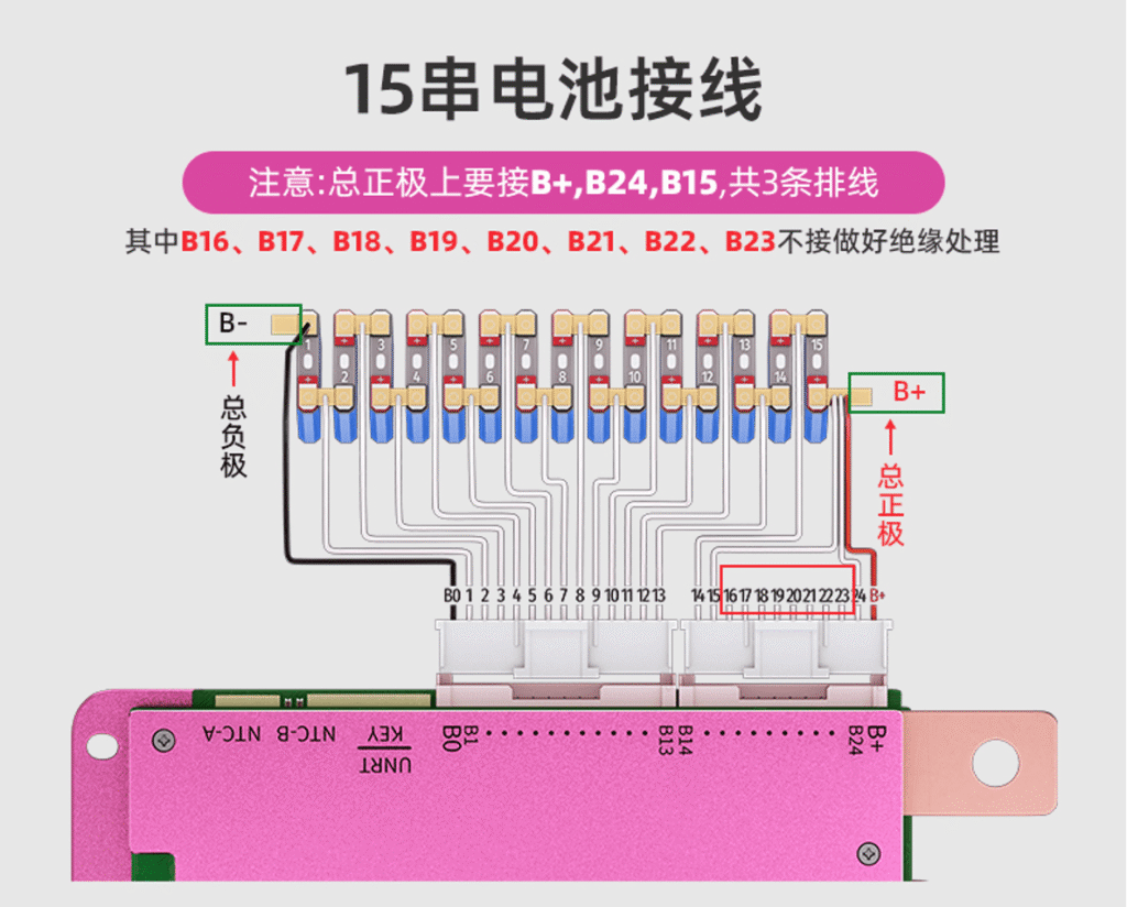
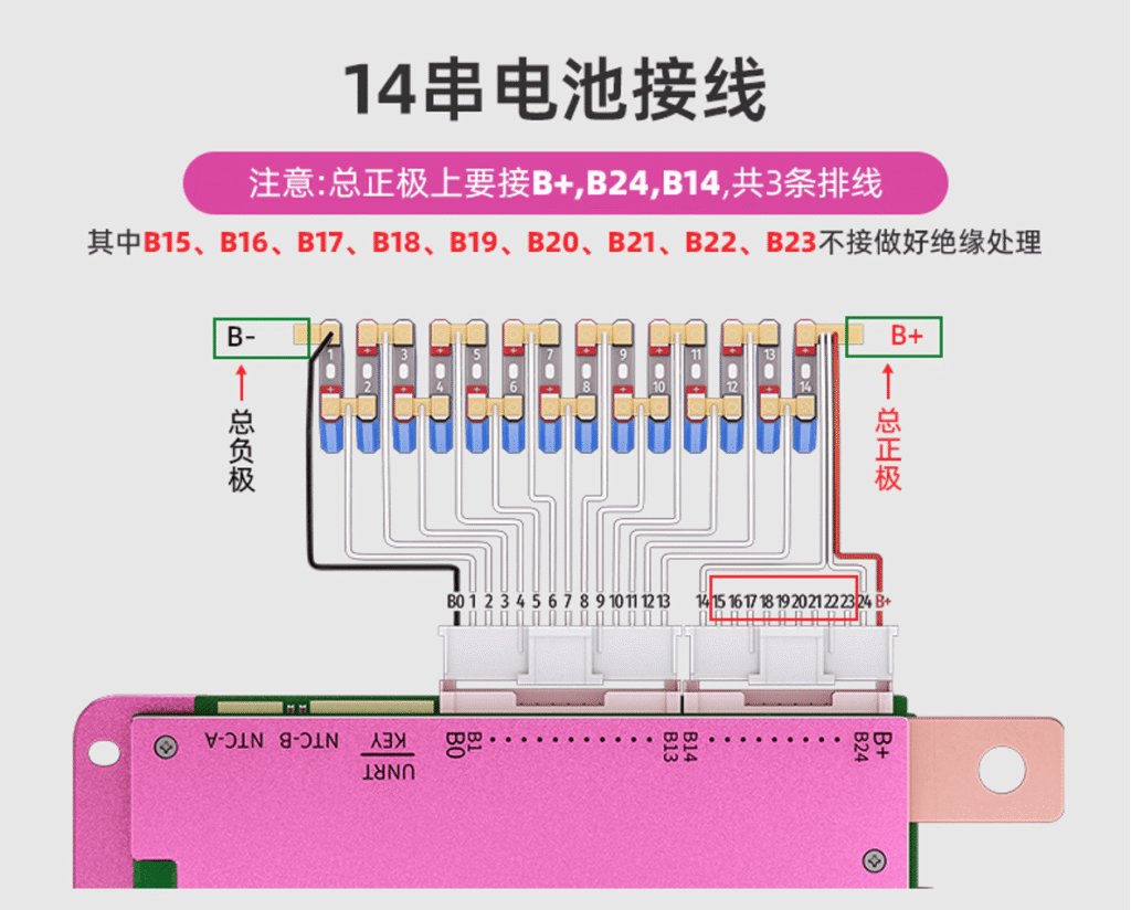
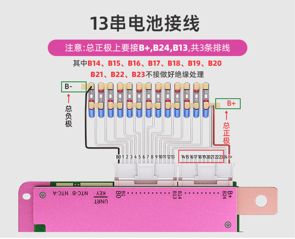
将黑色线焊接到电池B-(总负极),紧挨着黑色线的第一根白色采集线焊接到第一串电池的正极,后面依次将各串白色采集排线焊接每一串电池的正极,最后将B+线也焊接在最后一串(总正极)上。(参考说明书接线图)
Solder the black wire to the battery B- (main negative). Solder the first white sampling wire next to the black wire to the positive terminal of the first battery string. Then, sequentially solder each white sampling wire to the positive terminal of each battery string. Finally, solder the B+ wire to the last string (main positive). (Refer to the wiring diagram in the manual.)
② 检测电压
Check Voltage
使用万用表测量采集排线的针孔每串电压是否在正常范围内,如不正常,请检查接线是否有错焊、虚焊、假焊、漏焊等情况。
Use a multimeter to measure the voltage at each pin of the sampling ribbon for each battery string. If the voltage is abnormal, check for miswiring, cold solder joints, fake solder joints, or missed soldering.
③ 焊接输出线
Solder Output Wires
将B-连接线、C-连接线用螺丝锁至保护板对应的B-/C-螺母上,并拧紧螺丝,确保输出线连接稳定可靠,并把B-线焊接到电池总负极上。
Attach the B- and C- wires to the corresponding B-/C- nuts on the BMS board using screws, and tighten them to ensure stable and reliable connection. Solder the B- wire to the battery main negative.
④ 接入配件
Connect Accessories
如温控、电量显示灯、GPS、显示屏等插入对应的BMS接口,(参考说明书接口定义),最后将采样线插入保护板。
Insert accessories such as temperature control, battery level indicators, GPS, and display screens into the corresponding BMS ports (refer to the manual for port definitions). Finally, insert the sampling lines into the BMS board.
2. 激活保护板 / BMS Board Activation
① 上电激活
Power-On Activation
采样排线正确焊接并插入保护板后,保护板上电即可激活使用。
Once the sampling ribbon is correctly soldered and inserted into the BMS, powering on the BMS will activate it.
② 开关激活
Switch Activation
手动关闭BMS系统后,可通过短按按键开关激活BMS。
After manually turning off the BMS system, press the switch button briefly to activate the BMS.
③ 通讯激活
Communication Activation
手动关闭BMS系统后,可通过插入RS485显示屏激活。
After manually turning off the BMS system, insert an RS485 display to activate the BMS.
④ 充电激活
Charging Activation
通过充电器充电激活,(带通讯和电压检测的充电器除外)。
Activate by charging with a charger (excluding chargers with communication and voltage detection).
⑤ 短接激活
Short-Circuit Activation
通过万用表二极管档激活,红表笔接保护板动力线蓝线B-,黑表笔接动力线黑线C-。
Activate using a multimeter diode mode, connecting the red probe to the BMS power blue wire B-, and the black probe to the power black wire C-.
3. 手机APP下载及连接 / Mobile APP Download and Connection
① 通过扫描保护板上的二维码、应用商店、小程序搜索ANT BMS V2,或登录蚂蚁物联官网(https://download.antbms.com/)下载、咨询客服售后客服等方式下载并安装手机APP。
Download and install the mobile APP by scanning the QR code on the BMS, searching “ANT BMS V2” in app stores or mini programs, or visiting the ANT BMS official website (https://download.antbms.com/) and consulting customer service.
② 打开手机蓝牙和位置信息并进入APP,APP会自动搜索蓝牙BMS蓝牙名称,与保护板上的SN码前4位核对无误后点击蓝牙名称进入电池管理界面。
Turn on Bluetooth and location services on your phone and open the APP. The APP will automatically search for the BMS Bluetooth name. After verifying the first 4 digits of the SN code on the BMS, click the Bluetooth name to enter the battery management interface.
4. 参数设置 / Parameter Settings
首次使用时,需在APP或PC上位机设置电池类型及容量(出厂默认为铁锂参数),电池组的容量需要按实际容量进行设置。首次使用时需充满100%作为标定,其他保护参数可以根据自身需求进行设置,修改参数一级权限默认密码为00000000。
During first use, set the battery type and capacity on the APP or PC (factory default is LFP). The battery pack capacity should be set according to the actual capacity. Charge to 100% for initial calibration. Other protection parameters can be configured as needed. The default password for primary-level parameter modification is 00000000.
5. 指示灯状态 / Indicator Status
① 工作指示灯 / Work Indicator
- 绿灯快闪(4次/s):正常工作 / Green light flashes quickly (4 times/s): Normal operation
- 绿灯慢闪(1次/s):均衡中 / Green light flashes slowly (1 time/s): Balancing
- 绿灯慢闪(1次/4s):待机中 / Green light flashes slowly (1 time/4s): Standby
② 蓝牙指示灯 / Bluetooth Indicator
- 蓝灯常亮:BMS蓝牙已连接 / Blue light steady on: BMS Bluetooth connected
6. 蜂鸣器状态 / Buzzer Status
- 响一声:参数保存成功 / Beep once: Parameters saved successfully
- 长鸣:BMS出现保护,请及时检查 / Continuous beep: BMS protection triggered, please check promptly
7. 按键指示灯(选配) / Button Indicator (Optional)
① 开关机 / Power On/Off
按下开机,长按5s关机(长按关机功能,需要上位机勾选配置) / Press to power on, long press 5s to power off (long-press off requires configuration in PC software)
② SOC显示 / SOC Display
- SOC ≥80% 绿灯常亮 / Green light steady on
- 20 ≤ SOC <80% 橙灯常亮 / Orange light steady on
- SOC <20% 红灯常亮 / Red light steady on
③ 告警及保护提示 / Alarm and Protection
- 保护情况下红灯闪烁 / Red light flashes during protection
- 告警情况下橙灯闪烁 / Orange light flashes during alarm
(报警及保护信息见常见故障及处理) / (Refer to “Common Faults and Handling” for alarm and protection details)
8.集成电加热(选配)/Integrated electric heating(Optional)

①自动加热:充电状态下,检测到加热条件自动开启或关闭;
Automatic Heating: Automatically turns on or off when heating conditions are detected while charging.
② 加热异常保护:加热异常时,关闭充放电MOS,防止加热膜持续工作,保护电池安全;
Heating Anomaly Protection: In the event of a heating anomaly, the charge and discharge MOSFETs are turned off to prevent the heating film from continuous operation, thereby ensuring battery safety.
③加热异常告警:检测到加热膜异常时,APP告警提示;
Heating anomaly alert: When a heating film anomaly is detected, the APP issues an alarm prompt.
四、均衡开启条件 / Balancing Activation Conditions
| 检测内容 / Item | 默认参数 / Default Value | 单位 / Unit |
|---|---|---|
| 均衡开启电压 / Balancing Start Voltage | 铁锂:3.4 三元:4.1 / LFP:3.4, Ternary:4.1 | V |
| 均衡开启压差 / Balancing Start Voltage Difference | 10 | mV |
| 均衡结束压差 / Balancing End Voltage Difference | 2 | mV |
| 均衡条件 / Balancing Condition | 充电电流小于10A,且未发生单体欠压保护 / Charge current <10A and no single cell under-voltage protection occurred | — |
| 均衡电流 / Balancing Current | 持续800,最大1000 / Continuous 800, Max 1000 | mA |
六、 接口说明 / Interface Instructions

PCB上侧 / Top Side (from left sampling line to right DI/D0 direction)
采集高串 / High String Sampling
| 接口名称 / Name | Pin脚 / Pin | 标号 / No. | 定义 / Definition |
|---|---|---|---|
| B+ | 1 | 总正极采样线 / Total Positive Sampling | Battery pack main positive sampling line |
| B24 | 2 | 第24串电芯采样线 / 24th Cell Sampling | Sampling line of 24th cell |
| B23 | 3 | 第23串电芯采样线 / 23rd Cell Sampling | Sampling line of 23rd cell |
| B22 | 4 | 第22串电芯采样线 / 22nd Cell Sampling | Sampling line of 22nd cell |
| B21 | 5 | 第21串电芯采样线 / 21st Cell Sampling | Sampling line of 21st cell |
| B20 | 6 | 第20串电芯采样线 / 20th Cell Sampling | Sampling line of 20th cell |
| B19 | 7 | 第19串电芯采样线 / 19th Cell Sampling | Sampling line of 19th cell |
| B18 | 8 | 第18串电芯采样线 / 18th Cell Sampling | Sampling line of 18th cell |
| B17 | 9 | 第17串电芯采样线 / 17th Cell Sampling | Sampling line of 17th cell |
| B16 | 10 | 第16串电芯采样线 / 16th Cell Sampling | Sampling line of 16th cell |
| B15 | 11 | 第15串电芯采样线 / 15th Cell Sampling | Sampling line of 15th cell |
| B14 | 12 | 第14串电芯采样线 / 14th Cell Sampling | Sampling line of 14th cell |
采集低串 / Low String Sampling
| 接口名称 / Name | Pin脚 / Pin | 标号 / No. | 定义 / Definition |
|---|---|---|---|
| B13 | 1 | 第13串电芯采样线 / 13th Cell Sampling | Sampling line of 13th cell |
| B12 | 2 | 第12串电芯采样线 / 12th Cell Sampling | Sampling line of 12th cell |
| B11 | 3 | 第11串电芯采样线 / 11th Cell Sampling | Sampling line of 11th cell |
| B10 | 4 | 第10串电芯采样线 / 10th Cell Sampling | Sampling line of 10th cell |
| B9 | 5 | 第9串电芯采样线 / 9th Cell Sampling | Sampling line of 9th cell |
| B8 | 6 | 第8串电芯采样线 / 8th Cell Sampling | Sampling line of 8th cell |
| B7 | 7 | 第7串电芯采样线 / 7th Cell Sampling | Sampling line of 7th cell |
| B6 | 8 | 第6串电芯采样线 / 6th Cell Sampling | Sampling line of 6th cell |
| B5 | 9 | 第5串电芯采样线 / 5th Cell Sampling | Sampling line of 5th cell |
| B4 | 10 | 第4串电芯采样线 / 4th Cell Sampling | Sampling line of 4th cell |
| B3 | 11 | 第3串电芯采样线 / 3rd Cell Sampling | Sampling line of 3rd cell |
| B2 | 12 | 第2串电芯采样线 / 2nd Cell Sampling | Sampling line of 2nd cell |
| B1 | 13 | 第1串电芯采样线 / 1st Cell Sampling | Sampling line of 1st cell |
| B- | 14 | 总负极采样线 / Total Negative Sampling | Battery pack main negative sampling line |
通讯口 / Communication Port(Optional)
| 接口名称 / Name | Pin脚 / Pin | 标号 / No. | 定义 / Definition |
|---|---|---|---|
| B+ | 1 | 电池总正极/ Battery positive terminal | Battery positive terminal |
| SW- | 2 | 开机信号线 / Power-On Signal | Power-on signal wire |
| RXD1 | 3 | TTL通讯发送端 / TTL TX | TTL communication transmit |
| TXD1 | 4 | TTL通讯接收端 / TTL RX | TTL communication receive |
| VCC | 5 | 隔离电源5V / Isolated 5V Power | Isolated 5V power |
| GND | 6 | 隔离地 / Isolated Ground | Isolated ground |
| RS485A | 7 | 485通讯发送端 / 485 TX | 485 communication transmit |
| RS485B | 8 | 485通讯接收端 / 485 RX | 485 communication receive |
| CANH | 9 | CAN通讯高 / CAN High | CAN communication high |
| CANL | 10 | CAN通讯低 / CAN Low | CAN communication low |
DI/DO(Optional)
| 接口名称 / Name | Pin脚 / Pin | 标号 / No. | 定义 / Definition |
|---|---|---|---|
| DO1- | 1 | 输出信号- / Output Signal – | Output signal negative |
| DO1+ | 2 | 输出信号+ / Output Signal + | Output signal positive |
| DI1- | 3 | 输入信号- / Input Signal – | Input signal negative |
| DI1+ | 4 | 输入信号+ / Input Signal + | Input signal positive |
PCB下侧 / Bottom Side (from LED-key to NTC-2 direction)
LED-key(Optional)
| 序号 (No.) | 引脚 (Pin) | 功能描述 (Function Description) |
|---|---|---|
| 1 | B+ | 电池总正极 / Battery Pack Positive |
| 2 | SW | 开机信号/ Power-On Signal |
| 3 | GND | 地线/ Ground |
| 4 | LED-RED | 红灯输出线/ Red LED Output |
| 5 | LED-GREEN | 绿灯输出线/ Green LED Output |
NTC-1
| Pin脚 / Pin | 标号 / No. | 定义 / Definition |
|---|---|---|
| 1 | GND | T1温度线 / T1 Temperature |
| 2 | T1 | T1温度线 / T1 Temperature |
| 3 | GND | T2温度线 / T2 Temperature |
| 4 | T2 | T2温度线 / T2 Temperature |
NTC-2
| Pin脚 / Pin | 标号 / No. | 定义 / Definition |
|---|---|---|
| 1 | GND | T3温度线 / T3 Temperature |
| 2 | T3 | T3温度线 / T3 Temperature |
| 3 | GND | T4温度线 / T4 Temperature |
| 4 | T4 | T4温度线 / T4 Temperature |
GPS接口 / GPS Interface (from left to right)(Optional)
| Pin脚 / Pin | 标号 / No. | 定义 / Definition |
|---|---|---|
| 1 | B+ | 电池组总+ / Battery Pack Positive |
| 2 | RX | TTL接收端 / TTL RX |
| 3 | TX | TTL发送端 / TTL TX |
| 4 | GND | 地线 / Ground |
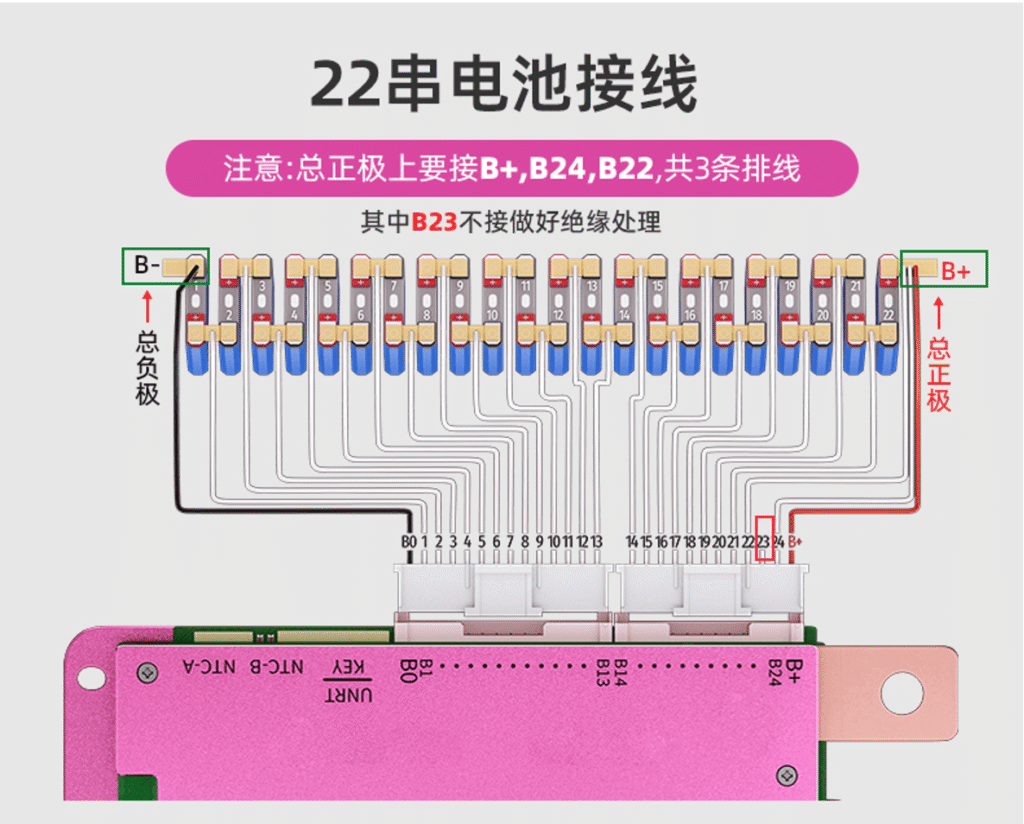
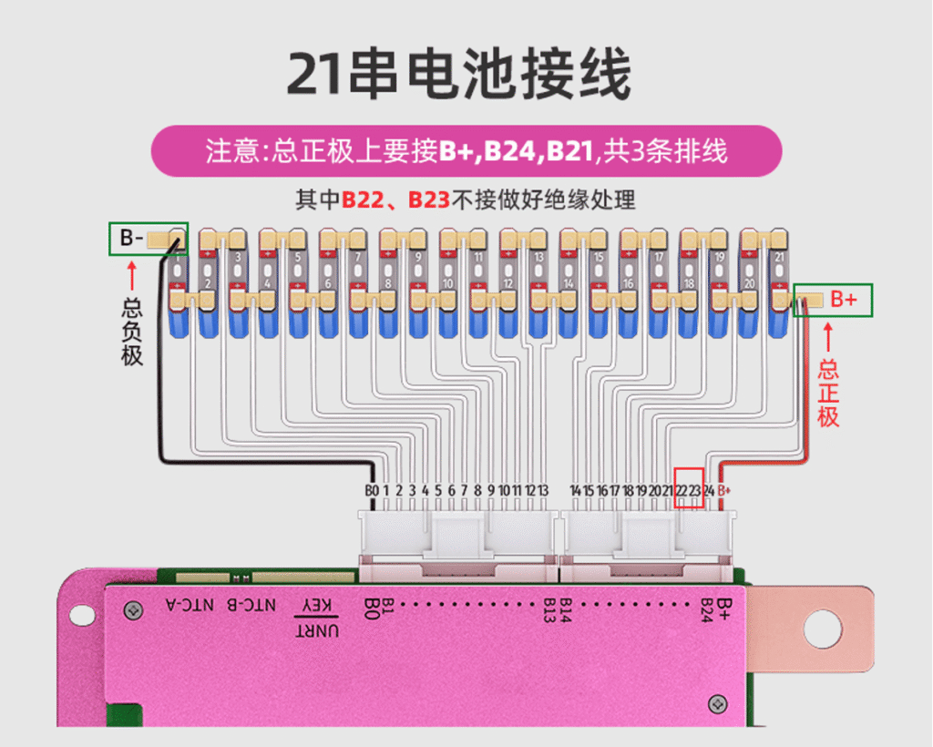
七、接线图 / Protection board wiring diagram
接线示意图

接线图/Wiring Wiagram
八、包装说明 / Packaging Contents
- 主动均衡保护板 1
Active Balancing BMS 1 - 采集排线 2
Sampling Harness 2 - 温控线 2
Temperature Sensor Wire 2 - 通讯线 1
Communication Cable 1 - 产品说明书 1
Product Manual 1
九、注意事项 / Precautions
- 本产品不支持采集排线跨箱体跳线使用。如因跨箱体连接导致的电路板烧毁、设备损坏等问题,我司不承担相关售后责任。
This product does not support the use of acquisition wiring harnesses across different enclosures.
Any damage such as PCB burnout or device failure caused by cross-enclosure wiring is not covered by after-sales service. - 焊接采样线时不可插着保护板,请根据电池实际串数进行焊接,多出的采样线无需焊接(多出的采样线请做好绝缘处理)。
Do not connect the BMS while soldering the sampling lines. Solder according to the actual number of battery strings. Extra sampling lines do not need to be soldered (please insulate any extra lines). - 焊接B-线时请把C-线做好绝缘处理,最后接输出端时再解除。
When soldering the B- line, insulate the C- line. Remove the insulation only when connecting to the output terminal. - 在没有充放电的状态下,保护板默认1800秒后待机,检测到充放电时会自动唤醒。也可通过APP或PC上位机修改待机时间,如设置0则代表不休眠。
By default, the BMS enters standby after 1800 seconds without charging or discharging. It will automatically wake up when charging/discharging is detected. The standby time can be modified via the APP or PC software; setting 0 means no standby. - 不同厂家的采集排线不通用,请确保使用蚂蚁公司配套排线。
Sampling lines from different manufacturers are not interchangeable. Please use the Ant BMS compatible lines. - 在测试、安装、接触和使用保护板时,要做好防静电措施。
Take proper anti-static precautions when testing, installing, handling, or using the BMS. - 不要使保护板的散热面直接接触电芯,否则热量会传送到电芯,影响电池的安全。
Do not let the BMS heat dissipation surface directly contact the cells, as heat transfer may affect battery safety. - 不可自行拆卸、更改保护板元器件。
Do not disassemble or modify the BMS components. - 组装作业中避免与外壳、电芯、镍带接触。
Avoid contact with the casing, battery cells, and nickel strips during assembly. - 我司产品进行严格的出厂检验测试,但是因为客户使用的环境不同(特别是在高温、超低温、太阳下、潮湿环境等),难免会出现保护板故障,所以客户在选择和使用保护板时,需要在友好的环境下使用,并选择一定冗余量的保护板进行备用。
Our products undergo strict factory testing. However, due to different customer environments (especially high temperature, ultra-low temperature, direct sunlight, or humid conditions), BMS faults may occur. Customers should use the BMS in suitable environments and consider having spare BMS units for redundancy.