Wiring diagram Of ANT BMS 10S-32S 80A-120A Smart BMS
Wiring diagram Of ANT BMS 10S-32S 80A-120A Smart BMS

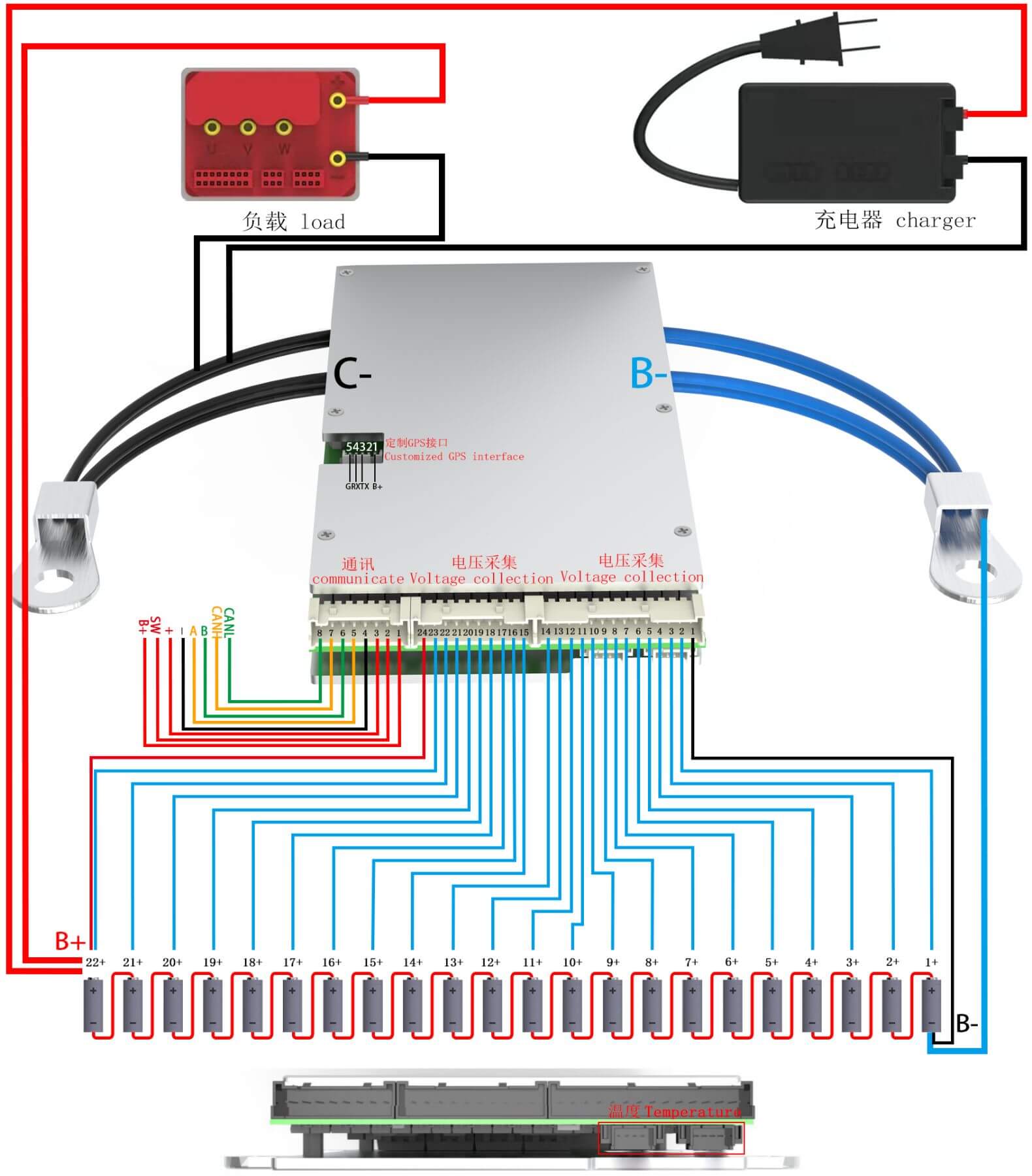
The wire label is B-, and it’s a blue-colored wire. Connect this wire harness to the battery’s negative pole.
When making the connection, be sure to connect B- to the battery’s negative terminal first before inserting the sampling line terminal. (Warning! Always connect B- to the battery’s negative pole first, or it may cause damage to the board).
The wire label is C-, and it’s a black-colored wire. Designed for the same MOS port, the charge and discharge negative poles share a single port. Connect C- to the negative terminal of both the charger and the load.
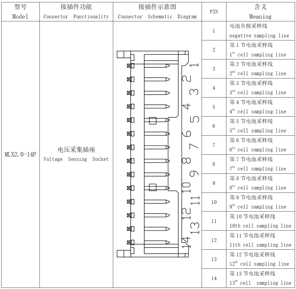
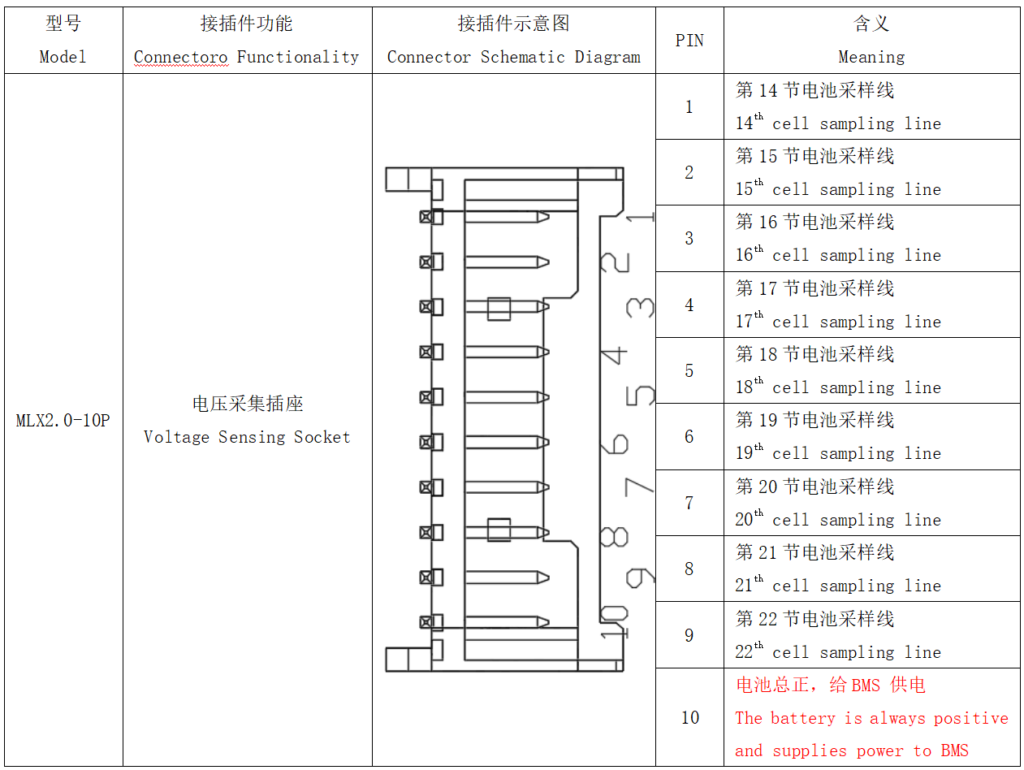
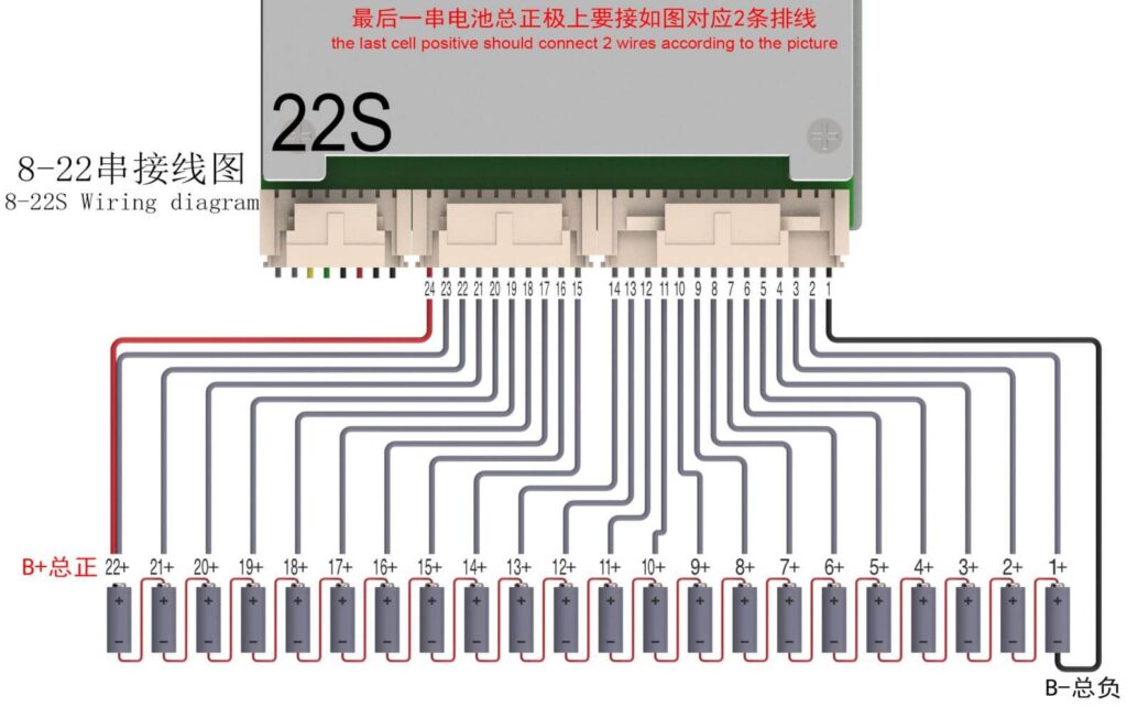
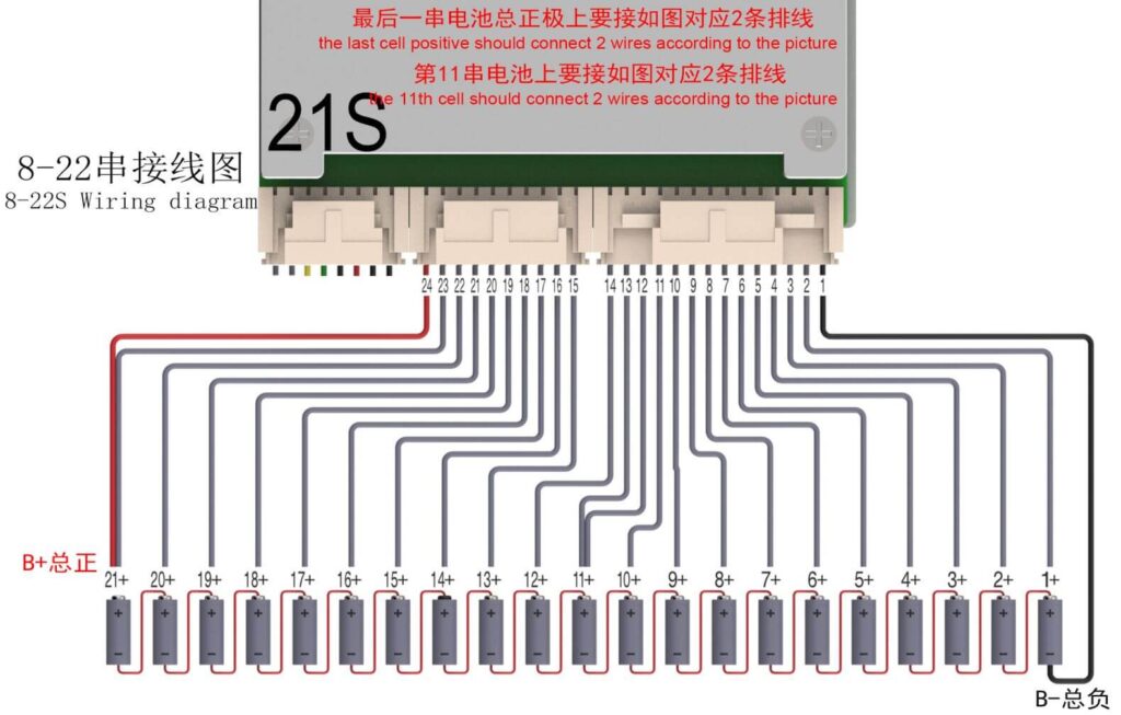
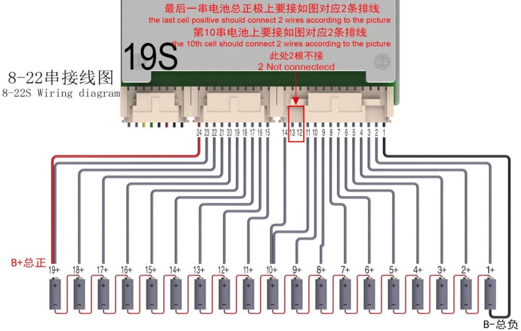
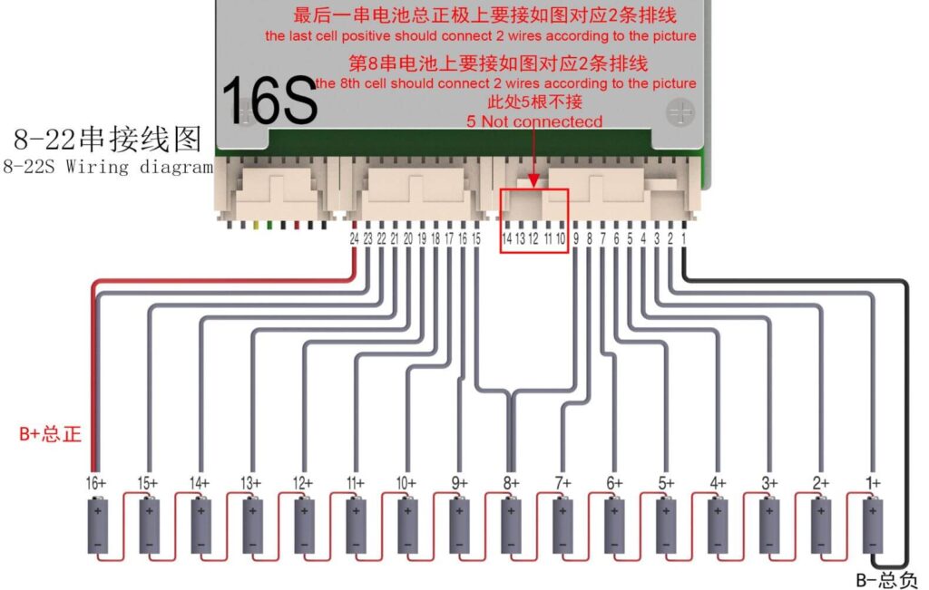
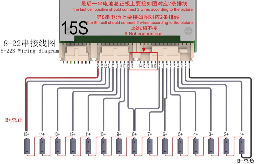
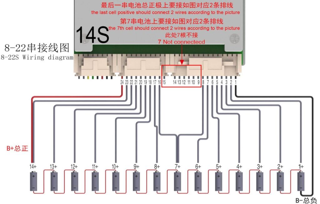
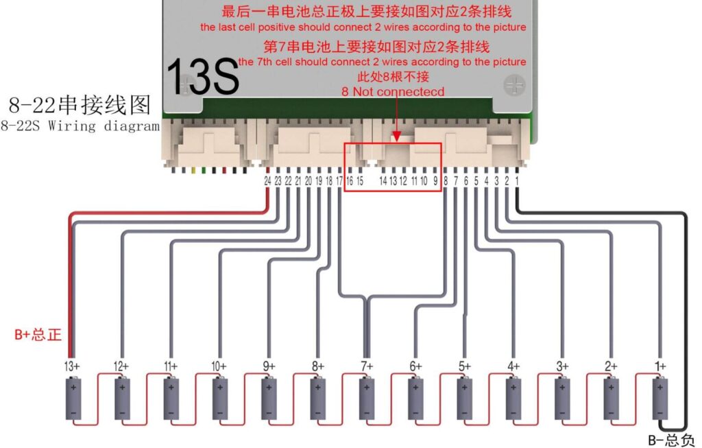
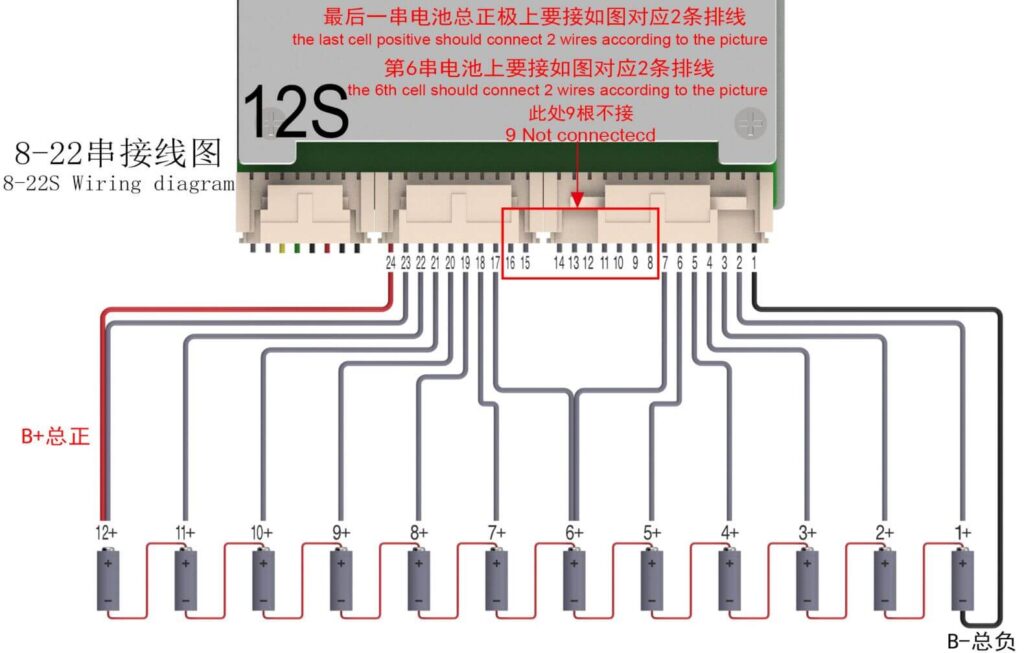
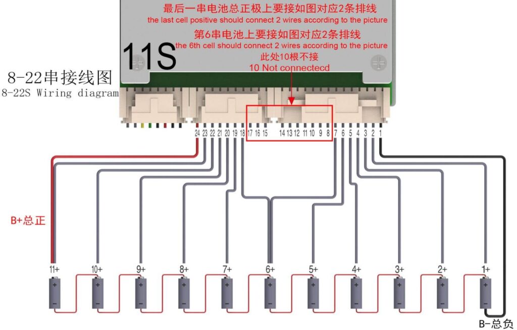
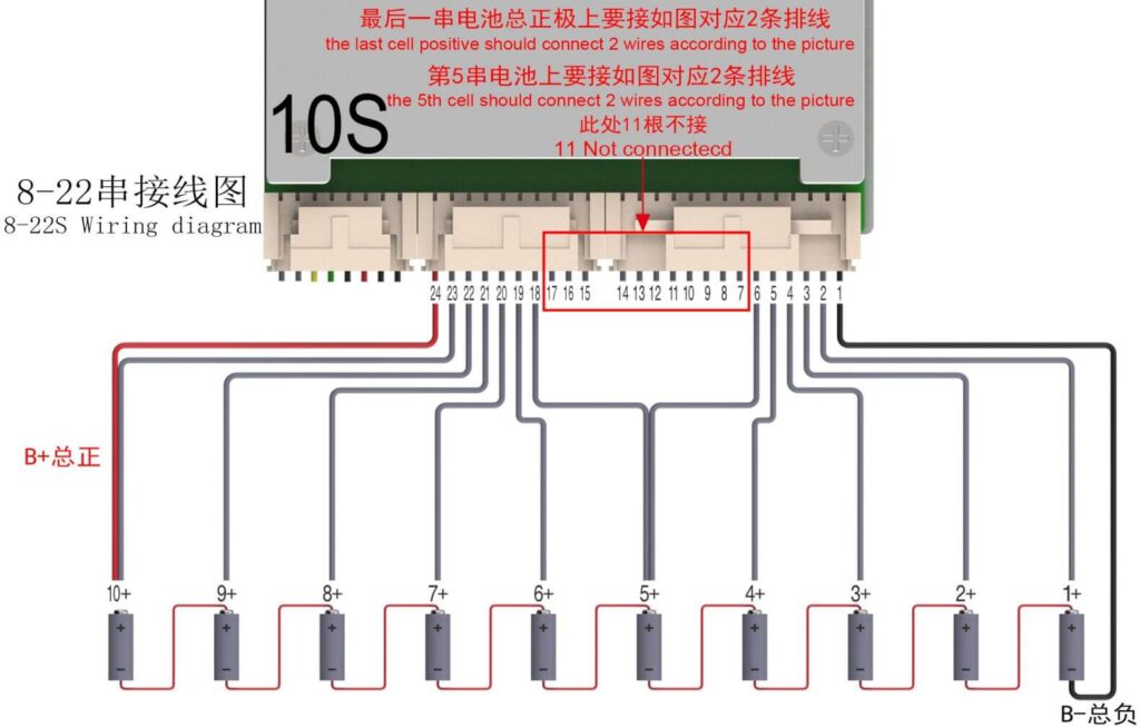
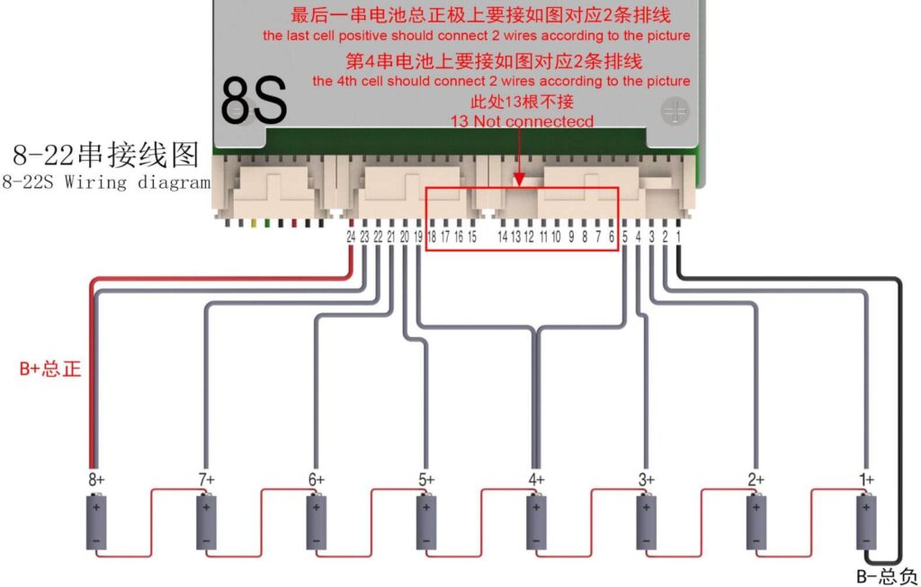
Consists of a wire harness for sampling the voltage of 22 series individual cells and the BMS power supply wire harness.
In total, there are 24 wires in the individual cell sampling wire harness and BMS power supply wire harness.


It needs to be activated first after Protection Board boot up. There are generally three methods:
1. Activation through charging with a charger, our protection board has a charging activation function (the charger should be without the communication and voltage detection features).
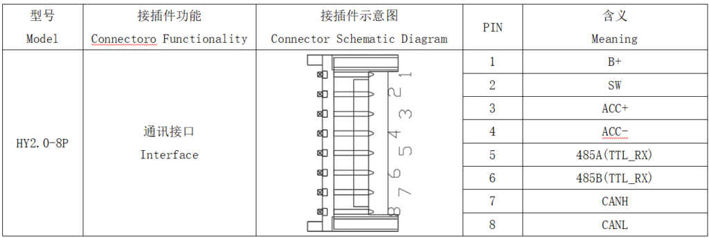
2. Activation through the communication interface by short-circuiting on SW and GND pins, for details, please refer to section Interface Definition.
3. Activation using a Multimeter in the diode mode, connect the red probe to the blue power line B- of the protection board, and the black probe to the black power line C-.