Wiring diagram Of ANT BMS 10S-32S 80A-120A Smart BMS
Wiring diagram Of ANT BMS 10S-32S 80A-120A Smart BMS

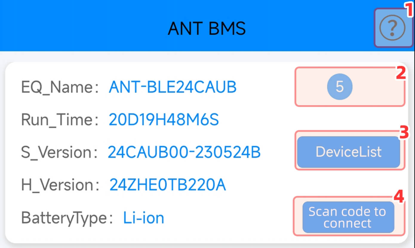 1. Click to jump to the full series product specification introduction page.
2. 5 means that the factory default is the maximum authority password of level5.You can directly modify the setting parameters and display the level 0~5 authority. Level0 is displayed when Bluetooth is not connected.Level 1 can only view the real-time status page.Level 2 can view the user’s parameter settings.Level 3 can set some parameters.Level 4 can modify more parameter settings.Level 5 is the largest and can replace 1-Level 5, all functions except key system parameters and configurations can be operated.
3. When the BMS is turned on for the first time,enter [Device List]to find the Bluetooth name starting with ANT,click on the name to select, and then click (OK/Sure)to make a Bluetooth connection.
4. After BMS is turned on and Bluetooth is turned on and there are no other devices nearby,you can use the QR code to quickly connect to Bluetooth.
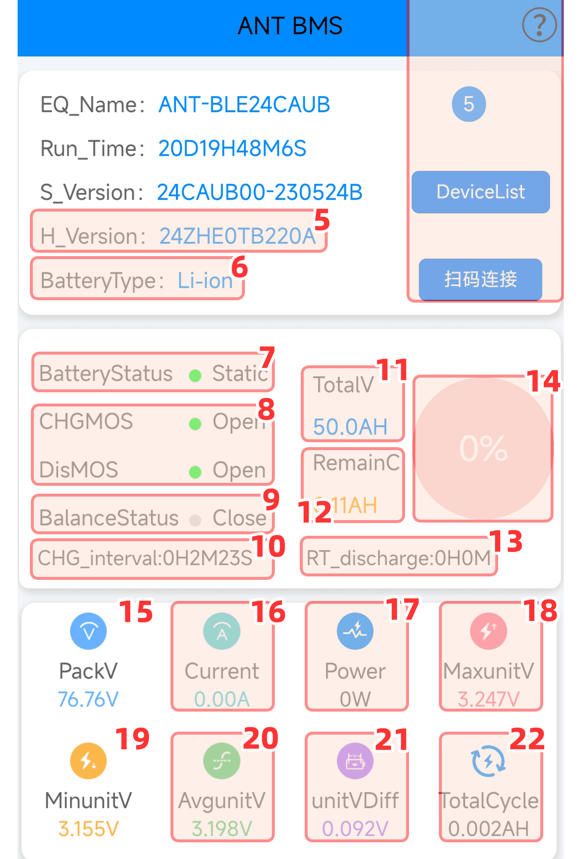
5. H_Version: Take 24S 220A peak 550A as an example:24 ZHE means 24 strings,ZHE solution,TB is the Bluetooth version,220A means the nominal current of the purchased product is 220A.
6. BateryTvpe: Display the battery type set by one click,which can display ternary,lithium iron and sodium batteries.
7. Display according to the current status of the battery:stationary,charging,standby, discharge,abnormal.
8. Display green on status,indicating that the current status is normal and can be charged and discharged by BMS.
9. Battery balancing will be automatically turned on when balancing conditions are met.
10. The length of time between the current time and the last charging.
11. According to the actual maximum capacity of the battery,the amount you set will be displayed.
12. Fully charged is equal to the total capacity. Calculate the remaining battery capacity based on the amount consumed by discharge.
13. Estimate how long it can be used based on the capacity and discharge current.
14. Estimated display of battery power percentage.
15. Average voltage*number of batteries in series = total voltage.
16. The charging current has a-sign in front of it, and the discharging current does not show any sign.
17. Total voltage*current =power,when charging, there is a”-“sign in front of it.
18. In real-time status,the cell with the highest voltage is displayed in red.
19. In real-time status,the cell with the lowest voltage is displayed in blue.
20. Total voltage/number of series connections =average voltage.
21. The voltage difference between the highest voltage of the unit and the lowest voltage of the unit.
22. Half of the charging current value and half of the discharging current value are accumulated For example,if a 50AH battery is fully charged from 0,it will be counted as 25AH. After being fully discharged,an additional 25AH will be added. The total cycle accumulation of 50AH means that it has been cvcled once.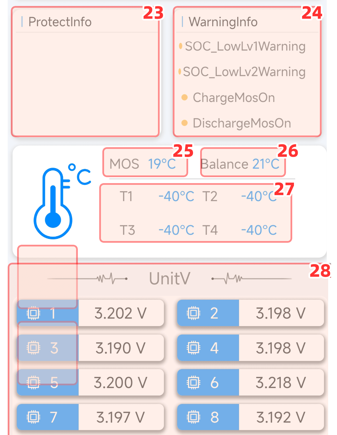
23. Display protection information for various reasons for power outage,used to analyze the cause of failure.
24. Display various warning messages for impending power outage protection (for example,the temperature control protection is 60 degrees Celsius and the warning is 55 degrees Celsius. When it reaches 55 degrees Celsius,it will first prompt a warning,and when it reaches 60 degrees Celsius,the protection will be triggered.
25. The built-in power of the protection board is MOS temperature controlled.If the temperature reaches 80 degrees Celsius,the power will be displayed as over-temperature.The protection will be powered off and the temperature will be restored if the temperature is lower than 65 degrees Celsius.
26. The protection board has built-in balancing temperature control.The balancing will stop when the temperature reaches 60 degrees Celsius,and will resume when the temperature reaches 60 degrees Celsius.
27. The external battery temperature sensor defaults to -40 degrees Celsius when not connected.Depending on the BMS version,a maximum of 2 or 4 sensors can be connected.
28. The protection board sets the corresponding number of series connections based on the actual number of batteries connected in series, and displays the single series voltage of each series-connected battery.
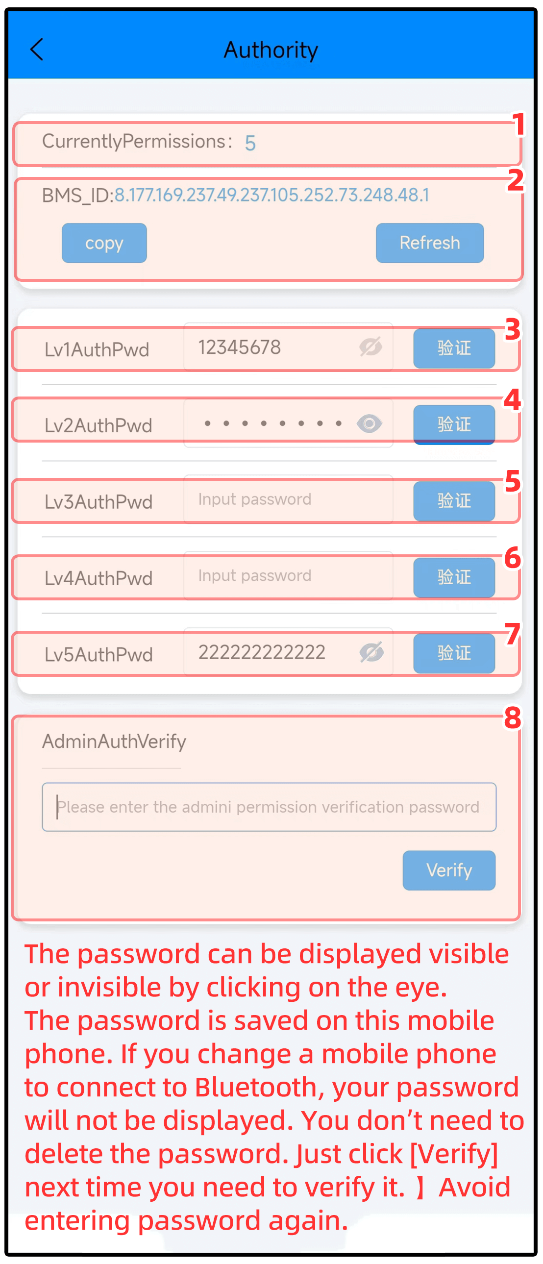
1. The factory default of the ANT BMS is current permission:5,which means there is no password and you can directly modify and set the basic battery parameters.
2. It is a string of dynamic password characters that can be refreshed. If the user changes the level 5 password and forgets the level 5 password he set, he can use this ID to retrieve the level 5 passwo- rd.Please see the operation process below ⑧
3. You can only view real-time status page inform- ation,but cannot set or modify any parameters
4. Can view user parameter settings,but cannot set parameters
5. Some parameter settings can be modified
6. You can modify more parameter settings and operate more buttons
7. I t has the highest authority and can replace lev- els 1-4. It can operate functions other than key system parameters and configurations
8. Click [Copy]to copy this string of characters from the chip ID and send it to the merchant. The mer- chant will reply to you with a string of characters in the same format. Copy and paste the charact- ers given by the merchant into [Administrator Permission Verification]and click [Verify],the device permission will display 9. At this time,you can modify the new 5-level permission password. The administrator’s 9-level permission is a dynam- ic password,which will become invalid after one operation. (You can also clear the running time, protection records and other information of the BMS)
It is convenient for customers to quickly set necessary parameters (the battery can be used normally after simple settings)to avoid looking for these parameters on the corresponding parameter page.
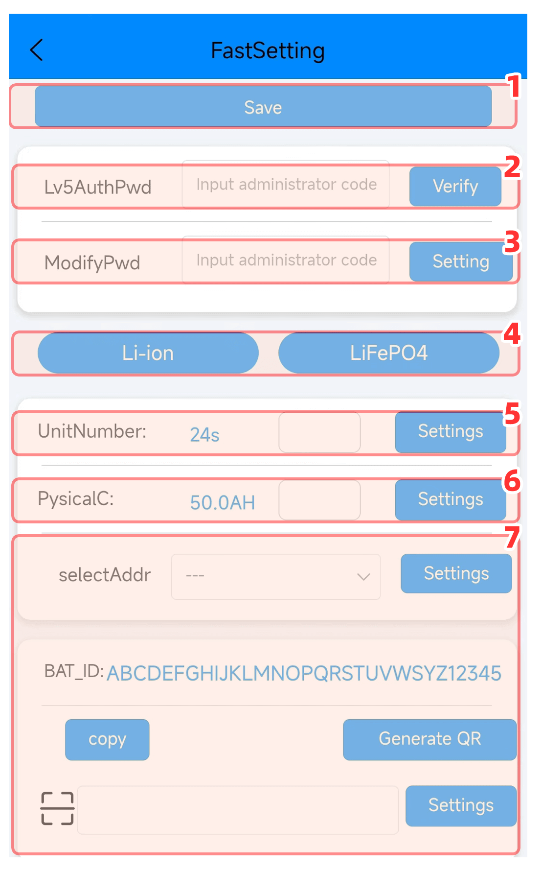
1. After setting and modifying parameters,you must click [Save Application Parameters]again for them to take effect.
2.When the protection panel is turned on for the first time,the default display is permission 5,which means there is no password and no verification is required.You can directly modify the setting parameters.
3.The new 12-digit password can only be entered when level 5 permission is displayed,then click [Settings]and then click [Save Application Parameters]above to take effect.Be sure to record the password after changing it,and change the parameters the next time you connect to Bluetooth.It will prompt that the permissions are insuf- ficient.You need to enter the 12-digit password you set after [Level 5 Permission Verification]. After successful verification,permission 5 is displayed before you can modify the setting parameters.
4.Quick settings can only set commonly used ternary and iron-lithium parameters with one click.Lithium titanate and sodium-lithium batteries need to be set on the BMS control page.
5.Set as many strings as the number of assembled lithium batteries in series.
6.Set the AH according to the total capacity of the assembled lithium battery.The purpose is to tell the BMS the maximum capacity of the battery.
7.This is for people with special needs.Please don’t modify it without authorization,just ignore it!
4.3V high voltage cell setting
First set the ternary lithium parameters with one click,and then modify the following parameters based on the ternary lithium parameters:
1.In [Voltage Parameters]:
Single unit overvoltage protection is modified to 4.3v The cell voltage recovery is modified to 4.2v,
The single secondary overvoltage protection is modified to 4.4v The monomer secondary overvoltage recovery is modified to 4.3v,
2.In [Equilibrium Parameters]:
The balance limit voltage is modified to 4.3v,
The balanced starting control voltage is modified to 4.2v during charging,
3.In [Battery Pack Parameters]:
The capacity calibration method is modified to 3,
All the following protection information can automatically change the value according to the cell type set with one click,and also supports manual modification of the protection value range (non-professionals,without obtaining reasonable and valid data,please do not manually modify detailed parameters without authorization to avoid danger.!Our company will not be responsible for any danger caused by unauthorized tampering with parameters.)
In total, there are 26 wires in the individual cell sampling wire harness and BMS power supply wire harness.
Take the ternary lithium parameters set in the picture as an example↓:
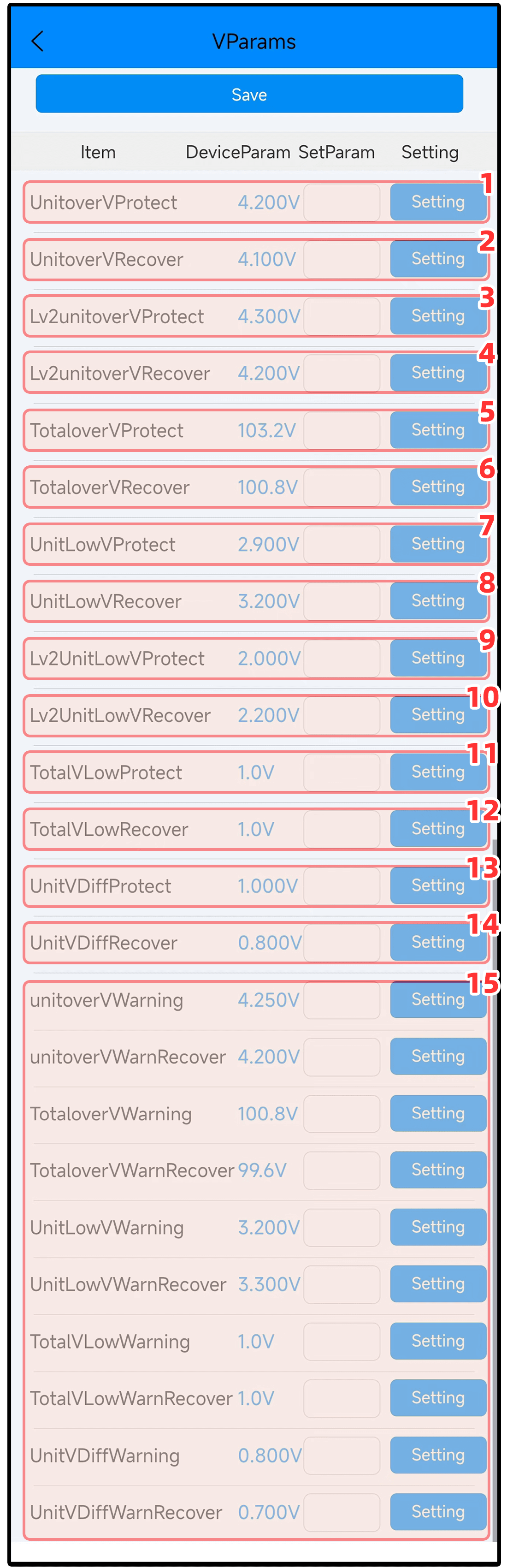
1. During the charging process,when the voltage of any string reaches this value,charging will stop and the power-off protection will not affect the discharge use (can be called first-level overvolt- age protection,with the largest protection weight). After protection,the voltage will generally be reduced. For example,when the ternary battery is charged to 4.2v and dropped to about 4.17 v;when iron lithium is charged to 3.65v and dropped to about 3.4v,it is normal(the amount of voltage reduction depends on many factors of the battery itself)
2. After the cell overvoltage protection is triggered, the protection can be released and the charging function can be restored only when the voltage and power consumption of all cells drops below this value.
3. Reaching this value indicates that the cell voltage has exceeded the first-level overvoltage protection. At this time,the power supply will be cut off and we are not allowed to use the charging and discharging functions. The protection can only be released by solving the second-level overvoltage protection. Secondary overvoltage protection reminds us that we must pay attention to it and check what causes the voltage to be instantly too high. Under normal circumstances,secondary overvoltage protection is not allowed (except for 4.35V high-voltage ternary batteries).
4. After the secondary overvoltage protection is triggered,the protection can only be released when the voltage returns below this value.
5. You can fill in the value based on the maximum value of the battery cell*the number of battery strings. The default value is 103.2V(which can be called three-level overvoltage protection). The parameters do not need to be modified because there is a first-level monomer overvoltage priority protection.
6. After the total voltage overvoltage protection is triggered,the protection can only be released when the voltage returns below this value.
7. During the discharge process,when the voltage of any string reaches this value,the discharge will stop and the power-off protection will not affect the battery charging. (It can be called first-level undervoltage protection,with the largest protection weight). The voltage will rise after protection, which is the same as the voltage reduction when fully charged.
8. After the cell undervoltage protection is triggered,the protection can be released and the discharge function can be restored only when the voltage of all cells returns to above this value.
9. Reaching this value indicates that the cell voltage has been lower than the first-level under-voltage protection. At this time,the power-off protection will occur,and we are not allowed to use the charging and discharging functions. The protection can be released only by solving the second-level under-voltage protection. Secondary undervoltage protection reminds us that we must pay attention to it and check what causes the voltage to drop too much instantly. Under normal circumstances, secondary undervoltage protection is not allowed.
10. After the secondary undervoltage protection is triggered,the protection can only be released when the voltage returns to above this value.
11. You can fill in the value based on the lowest limit value of the battery cell*the number of battery strings. The default is 1.0v(can be called the third-level undervoltage protection). This parameter does not need to be modified because there is a first-level single unit undervoltage priority protection.
12. After the total voltage undervoltage protection is triggered,the protection can only be released when the voltage returns to above this value.
13. If the cell pressure difference exceeds this value, the pressure difference protection will be displa- yed;at this time,the power will be cut off and we will not be allowed to use the charging and disch- arging functions.
14. After the voltage difference protection is triggered,the protection can only be released when the cell voltage difference returns to within this value.
15. The voltage alarm parameters corresponding to this column can be displayed in the [Real-time Status]alarm column. The alarm information only serves as a reminder.
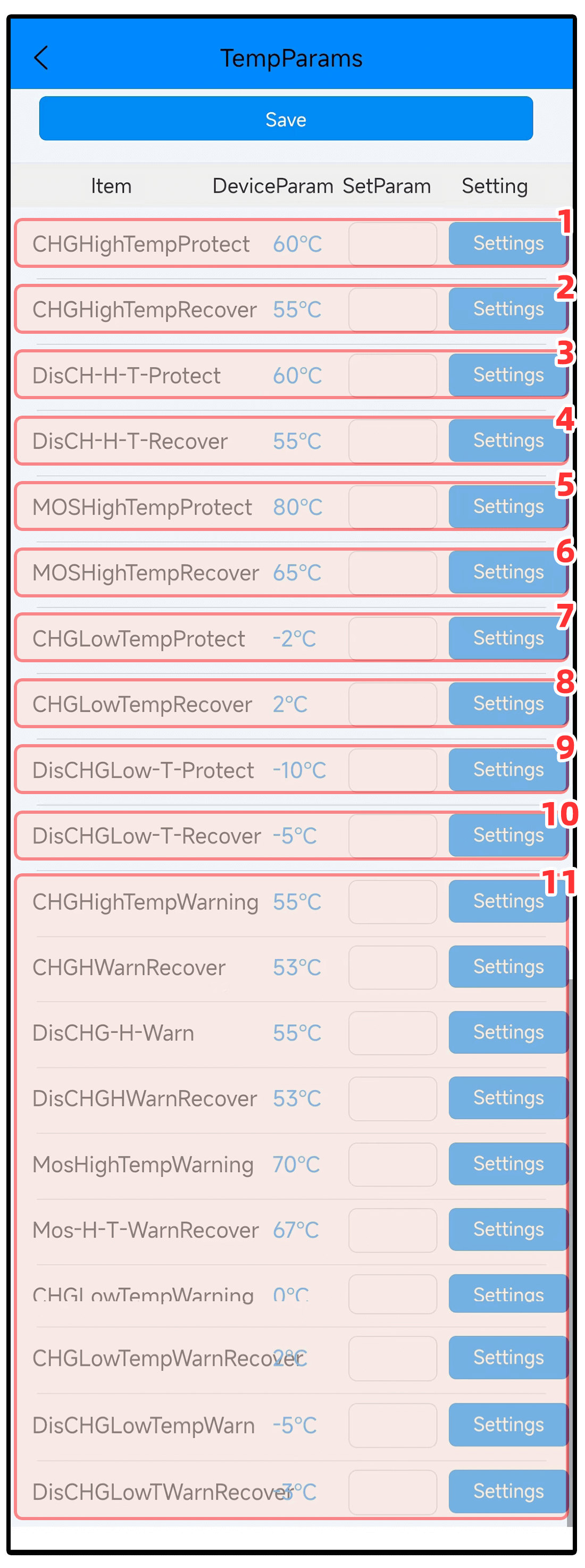 1. During the charging process,if the external battery temperature sensor detects that the battery temperature reaches 60℃,it will display the battery charging over-temperature protection. At this time,the power will be cut off and we will not be allowed to use the charging and discharging functions.
2. After triggering the battery high-temperature charging protection,the protection can only be released when the temperature drops below 55℃.
3. During the discharge process,if the external battery temperature sensor detects that the battery temperature reaches 60℃,it will display the battery discharge over-temperature protection. At this time,the power will be cut off and we will not be allowed to use the charging and discharging functions.
4. After triggering the battery high-temperature discharge protection,the protection can only be released when the temperature drops below 55℃.
5. During the charging process,the external battery temperature sensor detects that the battery temperature reaches -2℃ and will display the battery charging low temperature protection. At this time,the power will be cut off and we will not be allowed to use the charging and discharging functions.
6. After triggering the battery low-temperature charging protection,the protection can only be released when the temperature rises above 2℃.
7. During the discharge process,the external battery temperature sensor detects that the battery temperature reaches -10℃ and will display the battery discharge low temperature protection. At this time,the power will be cut off and we are not allowed to use the charging and discharging functions.
8. After triggering the battery low-temperature discharge protection,the protection can only be released when the temperature rises above -5℃.
*The above battery temperature protection parameters are only valid when connected to an external battery temperature sensor. Those without an external battery temperature sensor can be ignored. (T1,T2,T3,and T4 are displayed in the temperature area of the real-time status page to indicate the battery temperature. If no external temperature sensor is connected,the default display is -40℃. If the temperature sensor is extruded and deformed in the battery box,causing temperature detection errors,False protection,you can check how to shield [Battery Temperature Sensor Shielding]in [System Parameters]).
9. It is controlled by the built-in power temperature sensor of the protection board;regardless of charging or discharging,the greater the current and the closer to the power value of the protection board,the faster the temperature rises. When the MOS temperature reaches 80℃,the powerover-temperature protection will be displayed. At this time,the Power outage protection does not allow us to use the charging and discharging functions (triggering power high temperature protection means that the purchase options for the protection board are small and there is not much margin)
10. After triggering the power high temperature protection,the protection can be released only when the temperature drops below 65℃(if you want to release the protection quickly,you can manually adjust it to 70℃).
11. The voltage alarm parameters corresponding to this column can be displayed in the [Real-time Status]alarm column. The alarm information only serves as a reminder.
Non-professionals,please do not modify detailed parameters without obtaining reasonable and effective data to avoid danger!Our company will not be responsible for any danger caused by unauthorized tampering with overcurrent parameters!
Different current models have different parameter values Take the current parameters of the 24-string 130A [peak 325A]model as an example↓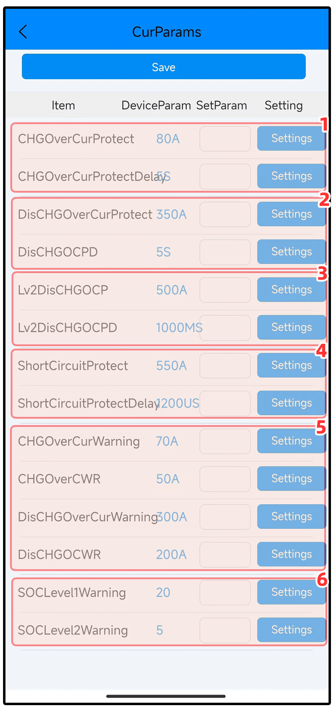 1. Indicates that the charging current exceeds 50A and lasts for more than 5 seconds,and the charging overcurrent protection will be triggered.
2. When the protection board detects that the discharge current is greater than 200A and lasts for more than 5 seconds,the discharge overcurrent protection will be triggered (can be called level 1 overcurrent protection,with the largest protection weight and priority to trigger protection). Why is the nominal 130A[peak value 325A]set like this? Because the load may generally reach 200-300A 1-2 seconds before starting, so we set a 5-second delay for the 200A overcurrent protection. There is a high probability that the protection will not be triggered. The protection board is rated at 130A and can support 130A or less for a long time if heat dissipation is done well. current,and ensure that there is a certain margin (ensure that there is enough margin for loading,climbing,and turning on the air condition er in summer). Otherwise,the greater the continuous current,the greater the heat generated by the power MOS. When the temperature of the power MOS reaches 80°C,it will When the power over-temperature protection is triggered,the power protection will be cut off and we are not allowed to use the charging and discharging functions. The protection can be released only when the temperature drops below 65℃.
3. When the protection board detects that the discharge current is greater than 300A and lasts for more than 1000MS (1 second),it will trigger the level 2 discharge overcurrent protection. Why do we need a level 2 discharge protection when thereis already level 1 protection? If the protection board selection is too small,you can more intuitively see the level 2 protection triggered and record the current reached. The purpose is to remind us that we must pay attention to it and further analyze whether we need to replace the protection board with a larger current. Level 2 overcurrent protection is not allowed under normal circumstances
4. When the protection board detects that the short-circuit current is greater than 450A and exceeds 1200US=0.0012 seconds,the short-circuit protection will be triggered. At this time,the power will be cut off and we will not be allowed to use the charging and discharging functions.
Release protection conditions:Disconnect the load that consumes battery power.
The short-circuit protection detected by the protection board is triggered at the microsecond level by an instantaneous large current. The system current measurement time is 1 second,which is tens of thousands of times different. Therefore, short-circuit protection occurs in many cases,but the APP displays the current as 0. Since the load is such as There is a large capacitor inside the vehicle controller (the voltage across the capacitor cannot change suddenly). When the positive and negative electrodes are directly connected to the battery,a very large current will be generated,usually hundreds or even thousands of amps.
This problem can also be solved by adjusting the short-circuit protection delay. The smaller the short-circuit delay is(meaning the shorter the time), the higher the detection sensitivity when short-circuit protection actually occurs. However,the instantaneous high current that charges the capa- citor at power-on increases the probability of triggering short-circuit protection. On the contrary, the larger the short-circuit protection delay is adjusted(meaning the longer the time),the lower the detection sensitivity will be,and the lower the success rate when a short circuit actually occurs. The probability of malfunction is also lower. Therefore,increasing the short-circuit delay mainly affects the sensitivity when short-circuit protection actually occurs,and has no impact on other operations of the system. If you often encounter short-circuit protection,it is recommended to increase the short-circuit protection delay by 200 each time until the short-circuit protection is no longer accidentally triggered,and then increase it by 500. This will not only prevent malfunctions, but also ensure that a short circuit actually occurs. time success rate.
5. The overcurrent alarm parameters corresponding to this column can be displayed in the [Real-time Status]alarm column. The alarm information only serves as a reminder
6. SOC is the estimated battery charge percentage in real-time state.
Set the physical capacity and full charge cycle, and the SOC percentage will be automatically calibrated.
When the remaining percentage of SOC power reaches 20%,a SOC level 1 alarm will be displayed, and there will be no power outage protection due to SOC alarm problems.
When the remaining percentage of SOC power reaches 5%,a SOC level two alarm will be displayed,and there will be no power outage protection due to SOC alarm problems.
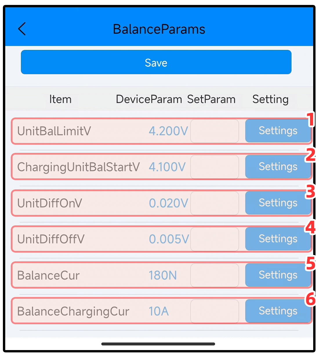
1. Cell voltages higher than this value will force the balance to open,which is called balance limit vo- ltage. If limit balance occurs in real-time,it means that the cell voltage has exceeded the normal cell overvoltage protection value. This reminds us that we must pay attention and check whether What causes the cell voltage to exceed the normal protection value. Under normal circumstances, extreme equilibrium is not allowed.
2. During the charging process,the balancing that is turned on when the cell voltage is higher than this value is called charging balancing(during the charging process,conditions ③and ⑥must be met at the same time before balancing can be turned on during charging).
3. During charging,the voltage difference is greater than this value(one of the conditions).
4. When balancing is turned on,balancing will stop,when the cell pressure difference reaches below this value.
5. 180N means that the balancing effect is 100%. If set to 90,the balancing effect is 50%(depending on the ability of the BMS hardware to support the maximum balancing current. The balancing current of all models of ant protection boards is basically 100MA, The balancing current of 10-24 strings is 200MA,the balancing current of 32 strings is 280MA)
6. During the charging process,the charging current must be less than this value and below 10A (one of the conditions)
To manually turn on the automatic equalization function:
On the BMS control page,you can manually click the [Turn on automatic balancing] and [Turn off autom- atic balancing] functions,which can be operated when the battery is not charged or discharged.
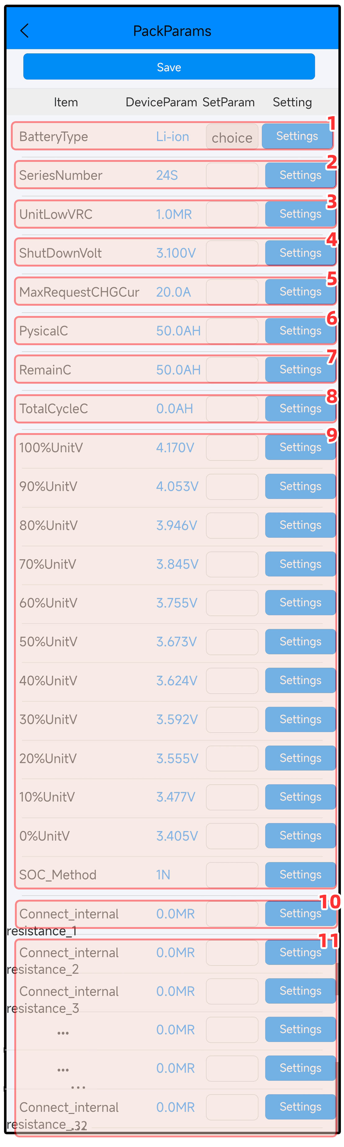
1. You can choose to set ternary,iron lithium,titanium lithium,and sodium electricity parameters with one click.
2. Set the corresponding number of series according in series.
3. Ignore,please do not modify without authorization.
4. If the battery is not used for a long time,it will automatically shut down for protection due to the self-consumption of battery power and the selfconsumption of power of the protective board,which consumes battery power and causes the cell voltage to reach 2.9V.
5. Ignore,please do not modify without authorization.
6. Set the actual total capacity of the battery pack according to the amp-hour capacity. Only by setting capacity the BMS can you know the maximum capacity value of the battery pack.
7. Under the premise of setting the physical capacity for example,the current available capacity of the battery is about 20AH,set it to 20,which is used to calibrate the remaining capacity percentage. It is basically usable without setting this parameter. Do not set this parameter when the percentage power display is accurate.
8. lgnore,please do not modify without authorization.
9. This is a basis for judging the remaining power percentage of COS. For example,when ternary lithium is fully charged to 4.2V,the voltage will be reduced to about 4.17V. If the BMS detects that the ternary lithium cell voltage is4.17v,it will be estimated that the power is 100%. A voltage of 4.053v will be estimated as 90%of the battery capacity. If it is a ternary lithium battery,set the physical capacity and let it sit for 10 minutes,it will automatically calibrate the remaining battery percentage. Fully charged will be regarded as 100%. If the pressure difference is large,the corresponding percentage of electricity will be reduced according to the size of the pressure difference. The amount of electricity consumed will be reduced according to the corresponding proportion.
10. lgnore,please do not modify without authorization.
11. If the connecting piece of series connected batteries between each string of lithium batteries is inconsistent in thickness and length,the corresponding batte ry may have a greater resistance. When the entire battery set is being charged,the voltage of the battery string with a larger resistance will always be higher than that of the other batteries. Voltage,after stopping charging,the voltage remains consistent with other voltages. The same is true fordischarge. The larger the current,the more obvious it is. You can compensate by setting the corresponding connection internal resistance. For example,the voltage of the 10th battery string is always 0.5 higher than other voltages every time it is charged. After V stops charging,it becomes consistent with other voltages. You can set the internal resistance of the 10th string to compensate. First set it to 2 and then observe the voltage jump to see if it is significantly reduced. Then set it to 4 and so on,until the internal resistance reaches the 10th level. Until the string voltage does not jump,the function of connecting the internal resistance can only be fine-tuned. If the internal resistance is too large,it can only be solved by the battery itself.
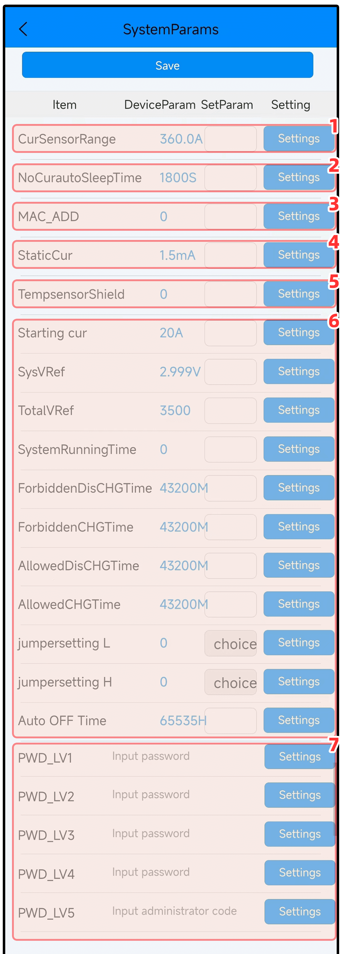
1. If the current detected by the BMS is not accurate with the actual value,you can use this value. Each time you increase or decrease it by 10,the current will become larger and smaller accordingly. Repeatedly modify the value to check the current until the displayed current is equal to the actual current. You need to Use a highprecision multimeter to measure,and the error range is within 5%.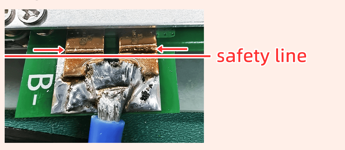 As shown in the figure,the thick blue wire at the B-end of the BMS is a shunt that detects current. Different types of shunts on the BMS have different shunts. If you remove the original wire and re-solder it,be sure to pay attention that the welding wire or solder cannot exceed this line. wire,otherwise it will affect the current detection accuracy. A trace amount of solder can adjust the parameter calibration. If the soldering wire exceeds the safety line or there is too much solder,a new shunt needs to be replaced.
2. If the BMS is not charged or discharged after being turned on,it will enter sleep mode after 1800 seconds. Sleep will only turn off Bluetooth,not shut down. When the protective board detects charging or discharging current,it will wake up Bluetooth immediately. (The length of standby time can be modified),standby can reduce the power consumption of the protection board.
3. Change the Bluetooth address number:it can only be numbers without letters,for example,change it to numbers 1 or 2 or 3 in order. After modifying the Bluetooth address,Bluetooth will be disconnected immediately. You need to re-search for the Bluetooth name with the corresponding code to reconnect to Bluetooth. This parameter is specifically for those who have many BMS of the same model in order to make it easier to find the BMS corresponding to the Bluetooth name.
4. lgnore,please do not modify without authorization.
5. If an external battery temperature sensor is connected,if the temperature sensor is shaken,squeezed,deformed and damaged in the battery compartment,resulting in inaccurate temperature,the ‘battery high temperature’or’battery low temperature’protection will be mistakenly triggered.
To block the T1 temperature sensor,set the number 1
To block the T2 temperature sensor,set the number 2
To block the T3 temperature sensor,set the number 4
To block the T4 temperature sensor,set the number 8
If you want to shield T1 and T4,add the shielding numbers 1 and 8=9 and set them in.
If you want to block all 4,add the numbers 1248 =15 and set them in.
6. System sensitive parameters,please do not modify without authorization.
7. The password for levels 1-4 is 8 digits, Level 5 password is 12 digits,
Enter a new password in the corresponding level password,click [Settings]and then click [Save Application Parameters]above to successfully change the password. You need to verify the password for level 5 permissions first,and the permission 5 can be displayed before you can change it.
If you forget your Level 5 password,please click here to view【2.1 Permission verification】
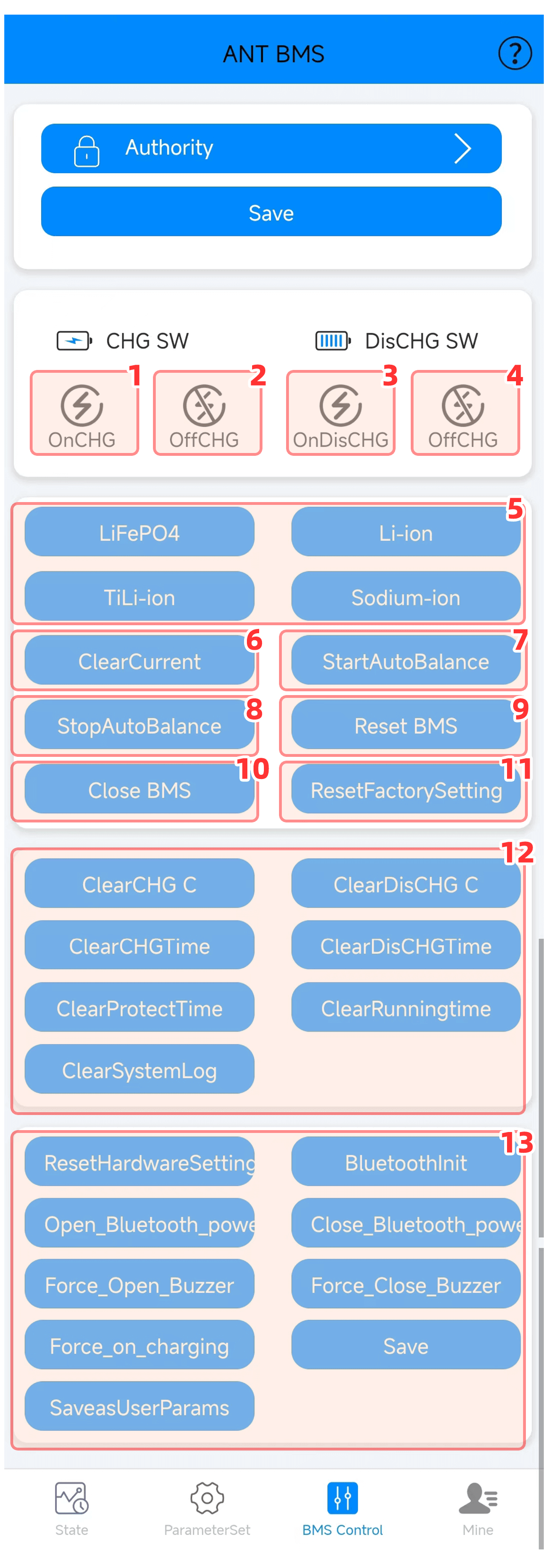
1. Manual operation control opens the charging MOS tube(the battery can be charged normally only after it is opened).
2. Manual operation controls the closing of the charging MOS tube (after closing,the charging current cannot reach the battery through the MOS tube).
3. Manual operation controls the opening of the discharging MOS tube (after opening,the load can use the battery power normally).
4. Manual operation controls the shutdown of the discharge MOS tube (the load cannot use battery power after shutdown).
5. Click the corresponding parameter to set it to the corresponding cell parameter with one click. After clicking to enter the parameter setting,you will find the parameter change. The original parameter will be restored after a few minutes. It will only take effect after clicking [Save Application Parameters].
6. In some cases,the current position displayed in the real-time status shows 0. several amps of current. If there is no actual load consuming current,you can click Current Zero to clear the current.
7. Manually turn on equalization. If the battery pressure difference is large,(you can click to turn on automatic equalization when without using the battery. Continuously balance when the balance is good, it will automatically stop when the balance is good)
8. Manually turn off automatic equalization.
9. BMS initialization refreshes current data.
10. Shutdown BMS. If you do not use the battery for a few months on a business trip, you can click to turn off the BMS to avoid selfconsumption of power and the battery will be exhausted. You can also fully charge the battery before placing it. After shutting down,you need to reactivate the BMS to turn it on. Use a charger to charge (the charger output voltage must be 2V or more higher than the current voltage of the battery pack to activate)or use a power-on cable to activate.
11. For example,after setting the ternary lithium parameters,and then modifying some of the parameters,click Restore Factory Settings to restore the ternary lithium parameters set with one click.
12. The corresponding data can only be cleared after verifying the administrator’s password for level 9 authority. The password for level 9 administrator authority is a dynamic password and becomes invalid after one-time operation.
13. You can only operate after verifying the administrator’s level 9 password. (If you verify level 9, please do not click and operate this section without authorization).
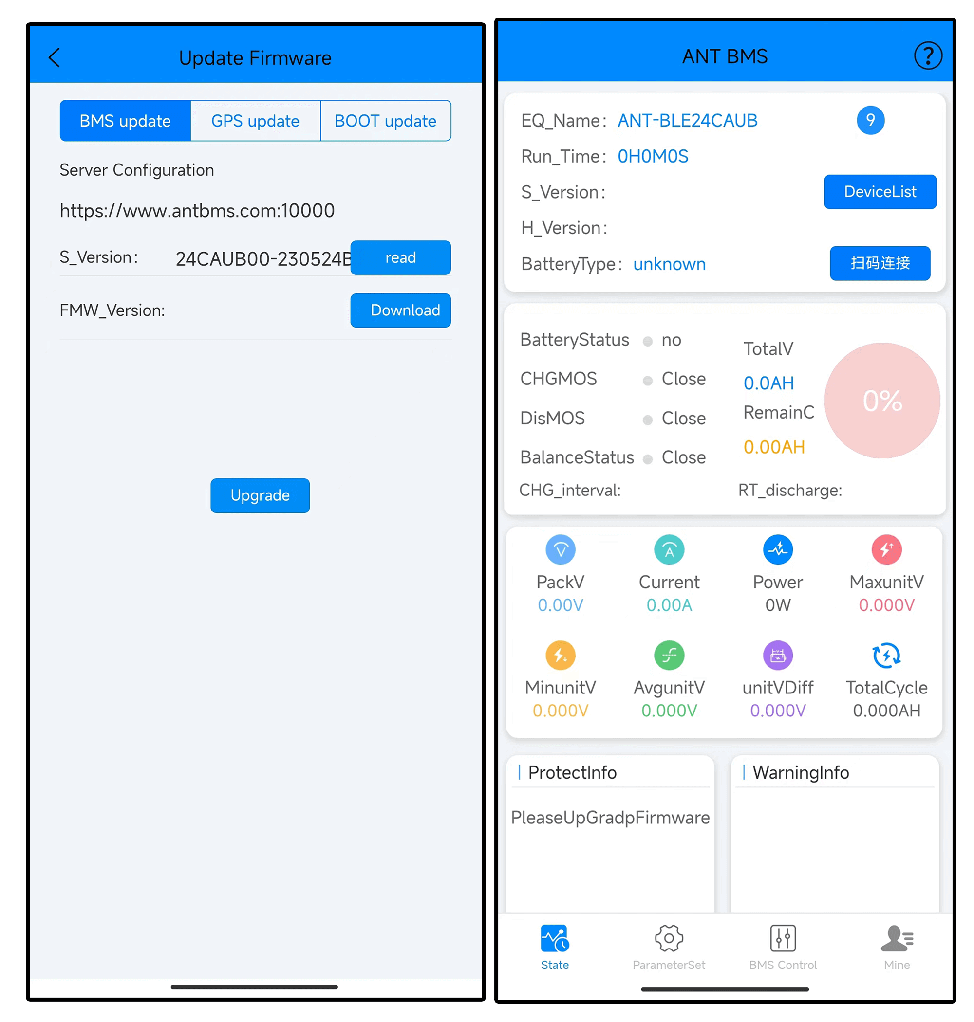
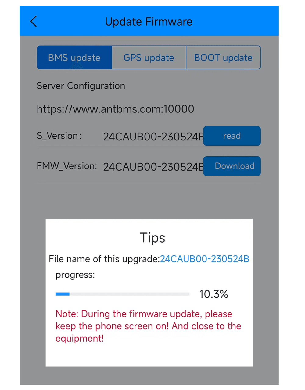
You need to connect to Bluetooth. As shown in the picture above,”Please upgrade the firmware”,enter [Me],[Firmware Upgrade],click ‘Read and Download,and then click ‘Start Upgrade’after the corresponding software number appears. Wait for the progress bar to complete the upgrade,and the program can The whole process from retrieval to restoration to normal is quite troublesome. If you don’t knowhow to operate it or can’t successfully upgrade it,you can only return it to the factory.
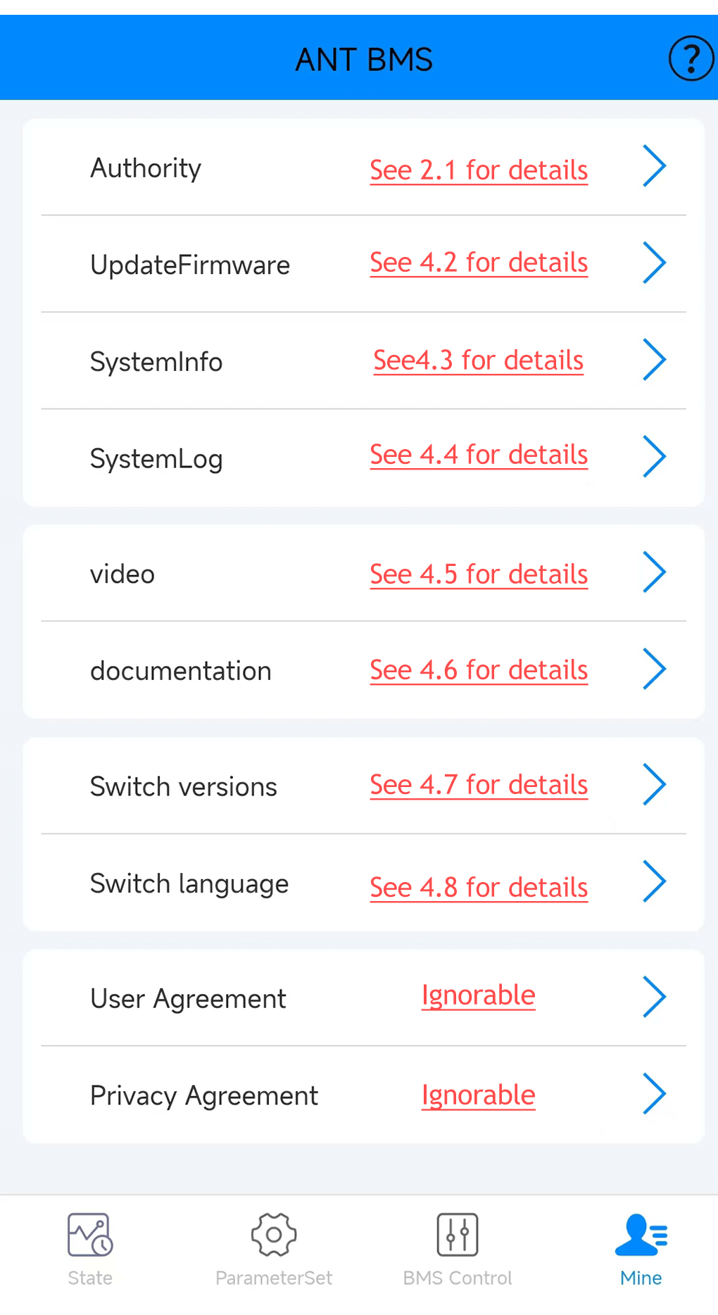
4.3 system message
Record the number of times corresponding to the protection project and the number of debugging parameters.
4.4 system log
Record historical preservation data.
Click [Upload]and note the file name here.It can be sent to the manufacturer’s server platform.Note the file name here.
And contact the manufacturer’s personnel to help check the protection information of this file,which can help analyze the cause of the protection failure remotely.
4.5 Video
Video to be improved…
4.6 Documentation
Full range of product specifications introduction page.
4.7 Switch versions
Ordinary users can choose the Bluetooth version to use.
Customized with GPS function,you can choose the online version. For rental cabinet projects,you can choose the rental version.
4.8 Switch language
Support Chinese and English language display switching.